Contactor Control via GPIO
CAUTION
Contactors can weld themselves together if handled improperly, which may result in high voltage being present on connectors even when the system is powered down. Always assume high voltage is present on any high voltage wiring. To ensure safety, unplug the wiring from the battery or remove safety disconnect switches before working on the system. Then measure with a multimeter to confirm the system is off.
Start by familiarizing yourself with how contactor and precharge circuits work. Here is a good whitepaper that explains how precharging works in great detail.
Automatic control 🤖~
The Battery-Emulator simulates an most of an entire car to get EV batteries to turn themselves on. Some batteries have CAN controlled contactors (e.g. Tesla, Kia, Hyundai) but some require hardwired signals (e.g. LEAF, Zoe) to turn on contactors and the precharge sequence. Battery Emulator can perform this with its feature called Contactor control via GPIO. This will automatically handle precharge, contactor closing, and optional economization.
It will also automatically open contactors when a critical FAULT event is encountered, if the FAULT event sticks for longer than 10 seconds contactors are opened. To recover from a latched fault, rebooting the emulator is required. You can then check which event led to the unrecoverable contactor opening via the Webserver events view. This improves safety for batteries that require manual control over the contactors, compared to manual on/off switches that will stay in their set state when a critical FAULT occurs. So to summarize, if you have a battery that needs hardwired signals for contactors, this feature is highly recommended!
Hardware requirements~
For the boards that were not designed specifically for Battery Emulator project, this is done by adding SSRs to some of the 3.3V digital output pins that are located on headers on most of the boards. Check out the pinout table for each board, which pins are defined for contactor control usage.
CAUTION
Be sure to use SSRs made for switching DC. Using an SSRs designed to switch AC will not work, these will latch while waiting for zero crossing trigger of the AC.
A good SSR choice is SSR-04-5DD-CN which is DIN rail mounted, has 4 channels with a LED on each.
NOTE
Hardware modules designed specifically for Battery Emulator, like BECom or Stark CMR, doesn't need SSRs since their dedicated outputs are rugged.
Software setup~
To enable the feature in the software, Enable the Contactor Control via GPIO option under Hardware Config, Save and reboot.
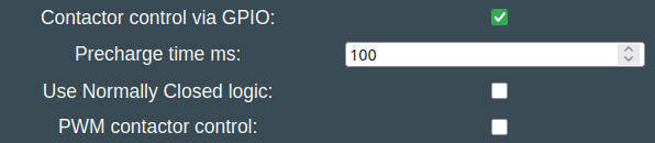
By default a 100 millisecond long precharge is performed. This value should be set to account for the resistance and capacitance of the inverter you use.
NOTE
Normally EVs perform a much more robust precharge, measuring motor inverter voltage and basing precharge duration based on this info, but since we dont have this info available a simple timer is used. Not optimal, but better than nothing!
TIP
There is also an option to use Use Normally Closed logic for very rare contactor setups, and should for 99.99% of users not be enabled.
PWM control for lower power draw 🧊~
Optional: It is also possible to reduce power consumption of keeping the big contactors engaged via PWM control. This requires Solid State Relays (SSR). The PWM signal will very quickly turn on/off the SSR, and still keep the contactor engaged. Do be careful, and test this properly before using it. It is very much depending on what SSR and battery contactor combination you use.
To use the PWM function, enable the PWM contactor control option
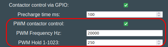
By default we use a Hold value of 250, which was tested to work well with Nissan LEAF contactors. Tweak this value to suit your contactors.
Benefits of PWM~
- Less load on the 12V supply
- Better for offgrid solutions where every Watt counts
- Less heat inside battery is good for summer
NOTE
PWM can only be used with electromechanical contactors. It's not applied to the BMS power control pin, despite that's also usually wired using a SSR.
Environment temperature can influence contactor hold strength when driven with PWM. Increase the PWM Hold value if you experience disconnects in extreme cold weather.
IMPORTANT
Ensure that the SSRs you choose support fast switching. If they don’t, they will likely fail within a short time with PWM enabled.
Example wiring diagram 🗺️~
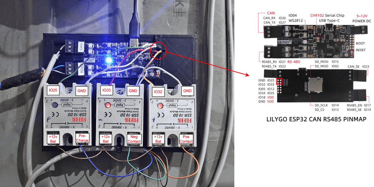
This schematic shows a wiring example with LilyGo T‐CAN485:
- Precharge pin 25 - Precharge SSR + input
- Positive Contactor pin 32 - Positive SSR + input
- Negative Contactor pin 33 - Negative SSR + input
- GND - All 3x SSR - input
Troubleshooting~
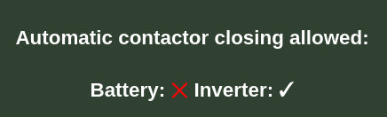
Before the contactors turn on, both Inverter and Battery needs to give OK ✅ signal. This can be verified via the Webinterface. In this screenshot, battery is preventing startup:
WARNING
In case the whole Emulator goes into Fault state, the contactors will open, and latch. To get them to close again, you need to restart the entire Battery-Emulator (after having analysed the fault)
You can check the Event view in the webserver, to see if any critical Error has been encountered.
TIP
If you observe after a longer time that the contactors open by themselves, increase the PWM Hold value relatively to PWM Frequency Hz, to ensure that they remain held steadily.
Overloaded GPIO pins~
In case the current draw on the GPIO pins is exceeded, like when you use an incompatible SSR, the webserver will show this:
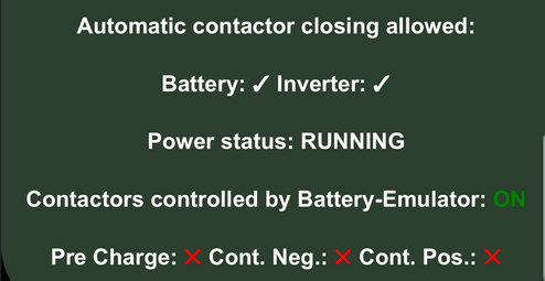
Note the "X" on the contactors, even though the emulator is in active state and should have contactors engaged. If you see this, remove the wires and restart the emulator, to confirm that activation of the pins is possible. Then switch to a compatible SSR.
CAUTION
Working with high voltage is dangerous. Always follow local laws and regulations regarding high voltage work. If you are unsure about the rules in your country, consult a licensed electrician for more information.