Ford Mach‐E
Ford Mach-E / E-Transit wiki~
Battery specifications~
A checkbox indicates that the battery has been tested and confirmed working.
- Mach-E Model years 2020-2022
- 75.7 kWh
- 98.8 kWh
- Mach-E Model years 2023-present
- 75.7 kWh NMC
- 78.2 kWh LFP 600kg ✅
- 98.8 kWh NMC
- E-Transit Model years 2022-present
- 66kWh net, 77kWh gross ✅
- 89kWh net

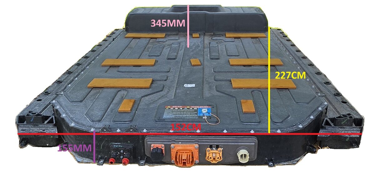
98.8kWh AWD Battery, from front side, showing battery dimensions and connections. Red is overall width, Yellow is overall length, Purple is height of short area, Pink is height of the hump to bottom of battery.
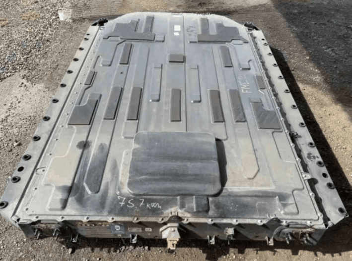
75kWh battery, from backside, showing only one HV connector
Wiring diagrams~
Wiring diagram, Low Voltage~
Warning - If BE powers down with contactors closed the contactors remain closed. Use Relay or Stark CMR to supply power to the BECM (BMS) to power down the BECM if Battery Emulator goes down.
A replacement LV connector can be purchased from AliExpress. aliexpress
Detailed LV connector C144 pin description.
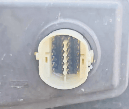
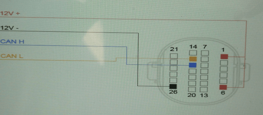
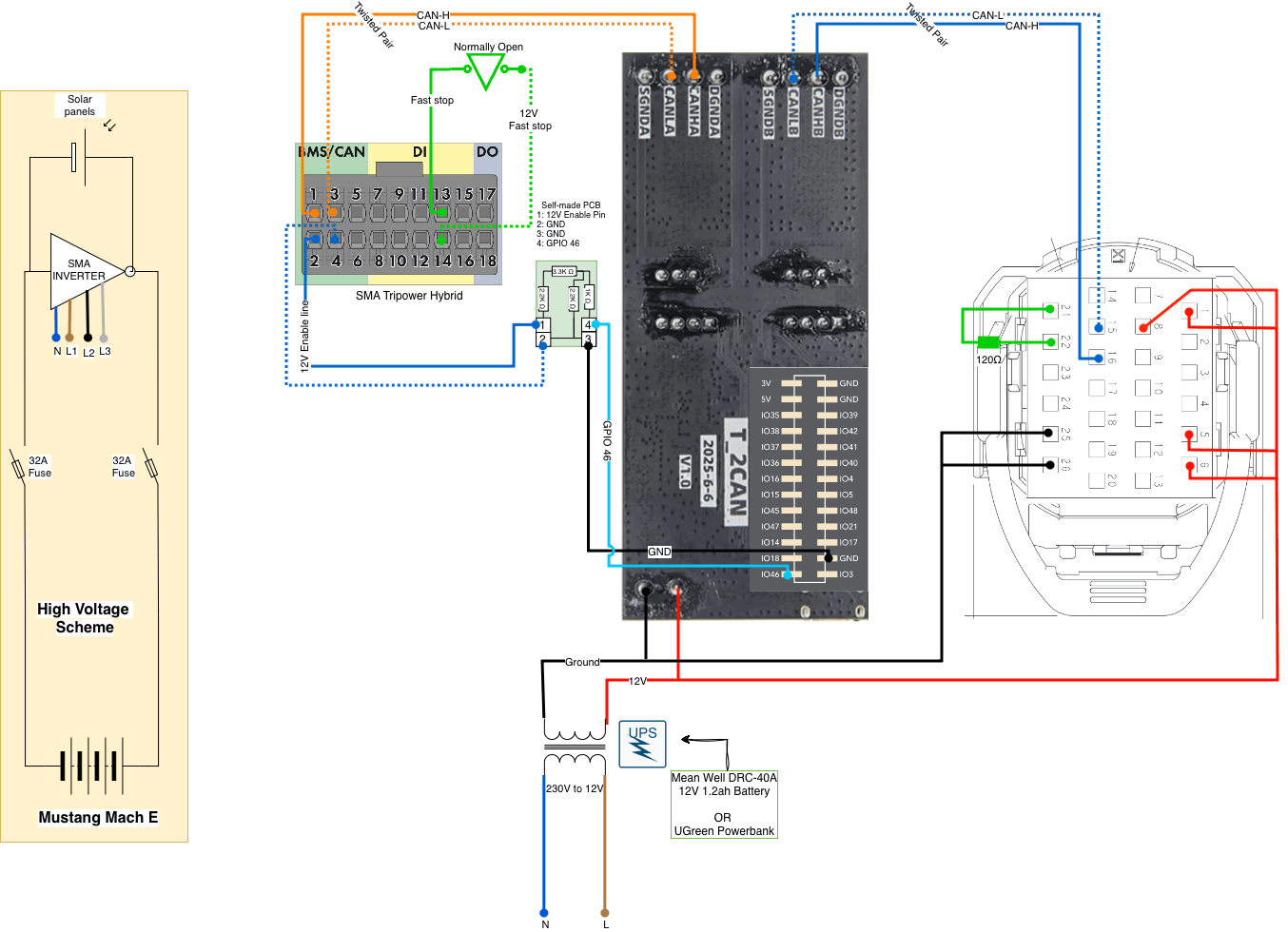
For communication only:
- Pin 1 to 12V constant (BMS+)
- Pin 6 to 12V constant
- Pin 26 to GND for 12V
- Pin 15 or 21 to CAN-L on Battery-Emulator
- Pin 16 or 22 to CAN-H on Battery-Emulator
For communication AND contactors:
- Pin 1 to 12V constant (BMS+)
- Pin 3 - 24 30ohm resistor (Coolant temperature sensor set to 25c)
- Pin 5 to 12V constant
- Pin 6 to 12V constant
- Pin 8 to 12V constant (Closing battery contractors)
- Pin 25 to GND for 12V
- Pin 26 to GND for 12V
- Pin 15 or 21 to CAN-L on Battery-Emulator
- Pin 16 or 22 to CAN-H on Battery-Emulator
Tip: use pin 15 and 16 for CAN Communication. Use pin 21 and 22 to add a 120Ω terminating resistor
Battery uses 1.4 amps to run the 12v 1mm2 cable should be enough.
Note: The battery does NOT contain a terminating resistor, so it is a good idea to add a 120 Ohm resistor between CAN-L and CAN-H on the battery side.
Wiring, High voltage~
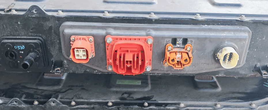
High voltage interlocks~
Jumpers need to be fitted on interlock detection pins, to make the battery believe the HV connectors are seated OK. The largest DC fast charge port does NOT need jumpering.
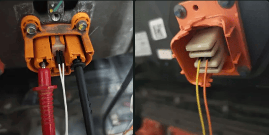
High voltage Isolation Monitoring~
Depending on the inverter, the inverter and Ford BMS may both operate their own high-voltage isolation-monitoring systems. These systems can interfere with each other: each system injects or measures signals relative to ground, so one monitor can make the other interpret the installation as having an isolation fault even when neither system would report a fault by itself. In effect, the two isolation-monitoring systems can fight each other.
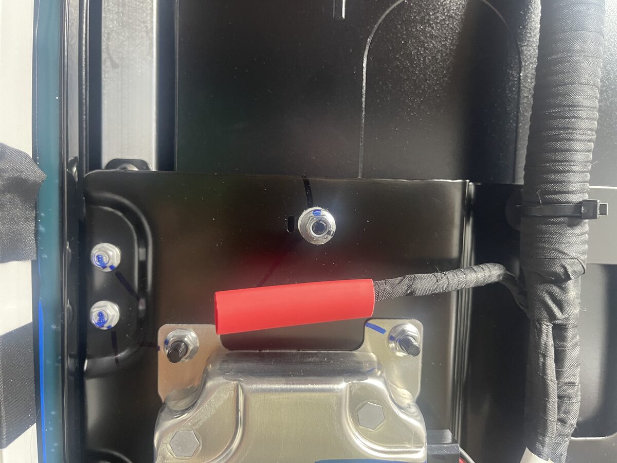
The confirmed experimental stationary-storage arrangement keeps the battery enclosure correctly connected to protective ground while disconnecting and insulating the Ford BMS isolation-monitoring ground/reference wire shown below. Y safety capacitors are not required for this arrangement.
WARNING
Removing and insulating the wire shown above the BMS has been confirmed to disable the battery's high-voltage isolation-monitoring function. The BMS may then be unable to detect a dangerous insulation breakdown between the high-voltage system and the battery enclosure, vehicle chassis or earth. This can conceal a potentially lethal electric-shock condition. Other effects of disconnecting this circuit are not yet known.
Treat this only as an experimental stationary-storage modification. Do not return a modified battery to a vehicle, transfer it to another person as an unmodified pack, or rely on the original BMS for isolation protection until the circuit has been restored and the complete isolation-monitoring system has been tested by a suitably qualified person.
The disconnected wire must be individually insulated, secured against movement and prevented from contacting the enclosure or any other conductor. The modification must be recorded in the system documentation.
Because there is no obvious external indication that isolation monitoring has been disabled, attach a durable, clearly visible warning label to the outside of the battery enclosure. Suggested minimum wording:
DANGER — HIGH VOLTAGE
BATTERY ISOLATION MONITORING HAS BEEN DISABLED
See the Battery Emulator Ford Mach-E / E-Transit wiki before servicing, moving or installing this battery.
Do not install in a vehicle until the isolation-monitoring circuit has been restored and tested.
The label should be weather-resistant, difficult to remove accidentally and positioned near the low-voltage/service connection or another location that will be seen before the pack is energised or installed.
Overview — location of the disconnected and insulated isolation-monitoring wire above the BMS:
![Overview showing the disconnected isolation-monitoring wire above the Ford BMS]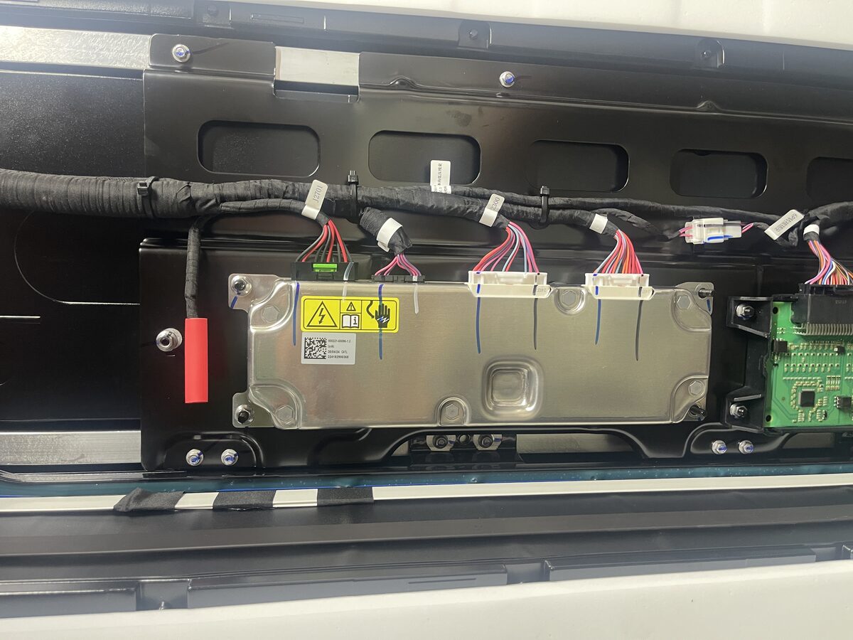
Detail — disconnected wire protected by red insulation:
![Close-up of the disconnected Ford isolation-monitoring wire with red insulation]
For further information about how insulation measurement values should be interpreted, check out the Insulation monitoring page.
Cell balancing~
LFP battery balancing~
Balancing has been physically confirmed on the 78.2 kWh, 108-series-cell LFP pack. The Ford BECM initiates balancing itself when the pack reaches a sufficiently high state of charge and presents enough imbalance. Battery Emulator does not need to transmit any of the experimental charging or charge-mode CAN frames for balancing to operate.
The following points have been confirmed during testing:
- The high-voltage isolation fault must be cleared. When an isolation fault is active, the BECM reports that maintenance rebalance was aborted because of a pack fault.
- The ten communication and coolant-related DTCs normally present in the current standalone installation do not prevent balancing.
- Balancing starts after the pack reaches a high state of charge with a significant cell/module deviation.
- Balancing continued while the pack was discharged at approximately 1-3 kW. It remained active after the cells returned to the normal flat operating region around 3.3 V with an instantaneous cell-voltage spread of only approximately 3 mV.
-
Continued balancing at only approximately 3 mV strongly suggests that the BECM is not controlling maintenance balancing solely from instantaneous maximum-minus-minimum cell voltage. The leading hypothesis is that it uses its calculated/learned module-SOC variation, or a balancing quantity derived from it, to decide how long the selected cells require bleeding.

-
Removing all optional experimental charging CAN frames did not stop balancing. The standard Ford Battery Emulator CAN implementation is sufficient once the BECM has decided that balancing is required.
- Actual bleed-resistor operation was confirmed independently by observing temperatures of approximately 60 °C on the active balancing resistors.
- An interruption to 12 V power stopped the test, but balancing could be initiated again after restoring power and returning the pack to the required state.
Useful BECM diagnostic data:
- DID
0x4818— Maintenance Rebalance Status: 0x04— Initializing0x01— In progress0x02— Successfully0x03— Aborted pack fault- DID
0x483E— Hybrid battery variation in state of charge between battery modules. This is a big-endian 16-bit value with a scale of0.002%per count. For example, raw value0x01D4is 468 counts, or0.936%, which FORScan displays as0.94%.
The 0x483E module-SOC variation is not the same measurement as subtracting the lowest instantaneous cell voltage from the highest. This distinction is particularly important for LFP cells because their voltage curve is very flat through most of their usable SOC range and becomes steep near the top.
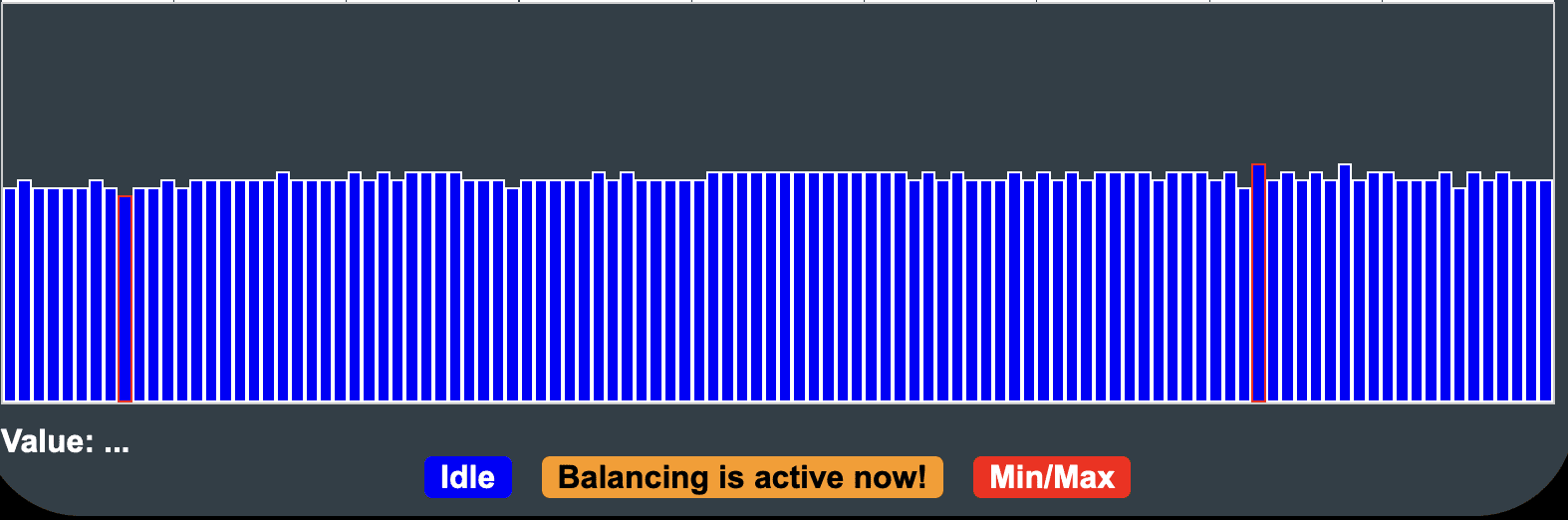
The Successfully state has also been observed when the pack had not been charged high enough for the upper LFP voltage knee to expose the larger imbalance. This may mean that the BECM considered the maintenance-rebalance request complete or found no balancing action necessary under those conditions. The exact completion criteria remain to be confirmed.
The balance resistors are marked 3680, corresponding to 368 ohm. PCB inspection suggests that two resistors may be connected in parallel for each balancing channel, giving approximately 184 ohm and 18.5-19.8 mA bleed current at 3.40-3.65 V. This connection remains to be confirmed electrically. With 225 Ah cells, the estimated continuous bleed rate would be approximately 0.21% cell SOC per 24 hours. Actual balancing may take longer because the BECM can duty-cycle channels or stop them according to voltage, temperature and time limits.
Still to confirm:
- Getting the pack into an official charge mode and automating the balance process (big task to do see lessons from BYD)
- Balancing has now been confirmed to continue at approximately 3 mV instantaneous spread in the flat LFP voltage region. Confirm how long it continues and which internal value eventually causes it to stop.
- Whether the BECM uses its calculated module-SOC variation (0.94% at the start of this test) to calculate a required balancing/bleed duration, rather than controlling balancing only from the live cell-voltage difference.
- Whether balancing stops after that calculated duration, or at a fixed maintenance-session time limit such as approximately 24 hours, even if the BECM still reports some module-SOC variation.
- The relationship between balancing finishing changing DID
0x4818fromIn progresstoSuccessfully, and cell deviation. - The exact voltage/SOC threshold at which the BECM permits balancing to start.
- Whether both
3680resistors in each apparent channel are electrically in parallel.
NMC battery balancing~
Balancing behaviour has not yet been characterized or physically confirmed on the Ford NMC packs. Do not assume that the LFP thresholds, maintenance-rebalance behaviour, resistor timing or required pack state also apply to the 75.7 kWh and 98.8 kWh NMC variants.
To confirm NMC balancing, record DID 0x4818, individual cell voltages, highest/lowest cell identity, pack SOC and balancing-resistor temperatures through a complete high-SOC charge and rest period. DID 0x483E should also be checked on an NMC pack to confirm that it uses the same scaling and meaning.
Faults stopping pack use~
If the battery 12 V is powered up with an interlock not connected when you try to get the contactors to close they will not.
This requires the DTC error clearing and then contactors will immediately close. DTC read/clear can be accessed from the More Battery Info page.

Missing HVIL~
If you see the DTC "U351B High Voltage System Interlock Circuit 'D' Low", you will get contactor opening during load. You will need to seat HVIL jumpers on the large DC connector.
3D-printable parts~
You can print your own 4 Pin C295 DC/DC Converter connector, check out the 3D‐printable parts page.
CAUTION
Working with high voltage is dangerous. Always follow local laws and regulations regarding high voltage work. If you are unsure about the rules in your country, consult a licensed electrician for more information.