Nissan LEAF / e-NV200
Software configuration~
For this battery type, use the option named Nissan LEAF battery under the Battery Protocol setting.
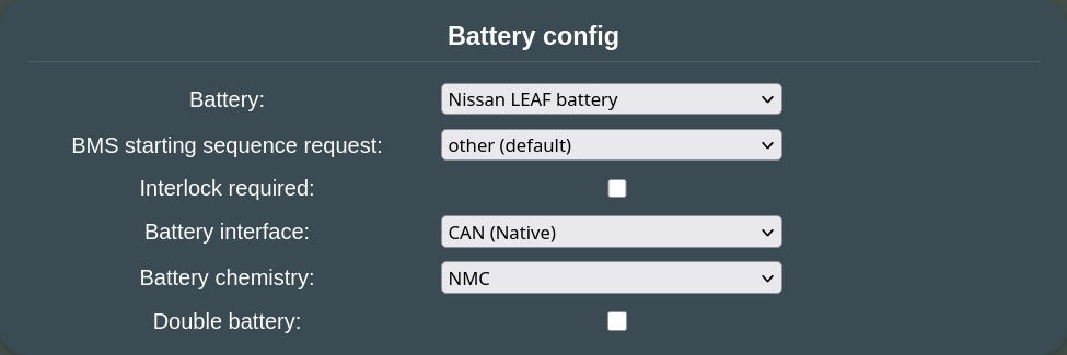
- leave the BMS starting sequence request setting at its other (default) value if this pack is newly deployed, or experiences high cell voltage deltas (> 150mV). You can start experimenting with the other settings when you gained some experience on how balancing and degradation performs over time (using some monitoring solution over MQTT, like for example Home Assistant to observe behavior is strongly recommended when using experimental settings). Changing this setting requires a BMS reset.
- on a ZE0 (2011-2012 24kWh) battery, you can enable Interlock required for extra safety. The system checks that the original high voltage connectors and SDS are properly seated in before you can start.
- If you enable this setting on a AZE0 or ZE1 (2013-2023) battery, both HV plugs need to be seated (80kW motor and 6kW heater). Thus for these it is recommended to not use Interlock required due to the inconvenience of having to source both HV connectors (and insulate manually one of them). Instead just block off the unused HV port with a 3D printed cover.
- set the Battery chemistry to NMC.
TIP
BMS starting sequence request set to nomral charge (experimental) avoids overbalancing when your pack is in a good shape (small cell voltage delta in your preferred SOC range).
Wiring diagrams 🔌~
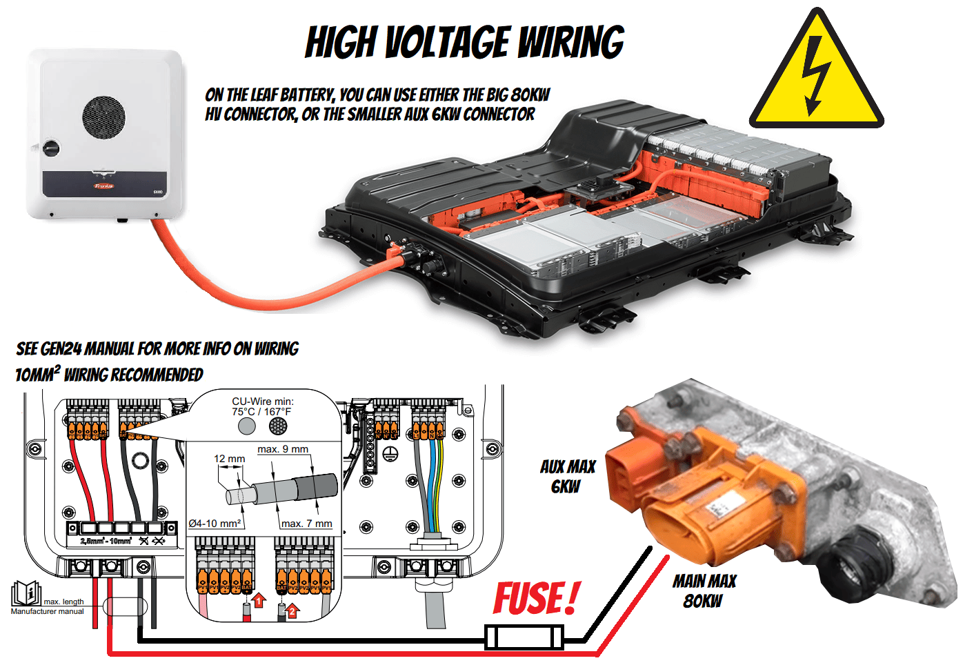
The following pictures show an example of hooking up a LEAF battery to a Fronius Gen24 inverter. The same diagram can be useful for planning other inverter combinations.
NOTE
The LEAF battery requires a 12V supply capable of delivering at least 1.5A.
Remember to seat the service disconnect switch. Without this fitted, the battery will not output any voltage when contactors are closed. This is how the SDS is used (Youtube).
High Voltage connection (energy)~
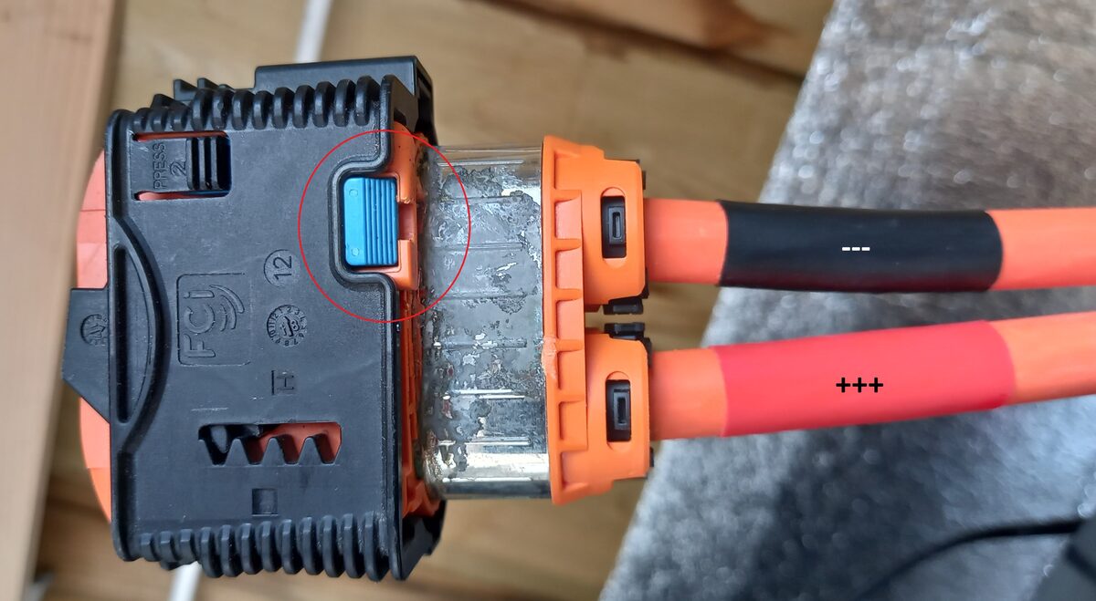
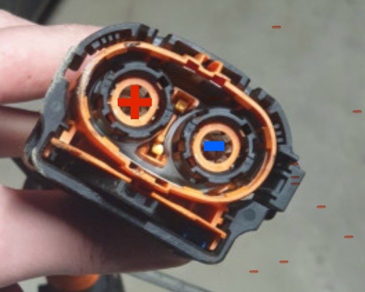
The Positive (+) wire is close to the data port and the Negative (-) wire is close to the PTC High Voltage port (Aux Max 6kW).
TIP
Check out our High Voltage wiring page with examples on how to make the connections safely.
Low Voltage connection (control and data)~
This example diagram shows how to connect a LilyGo T‐CAN485 to a Nissan LEAF AZE0/ZE1 pack (with a Yazaki 36pin connector), using automatic contactor control via solid state relays, also featuring periodic BMS reset and an optional equipment stop circuit.
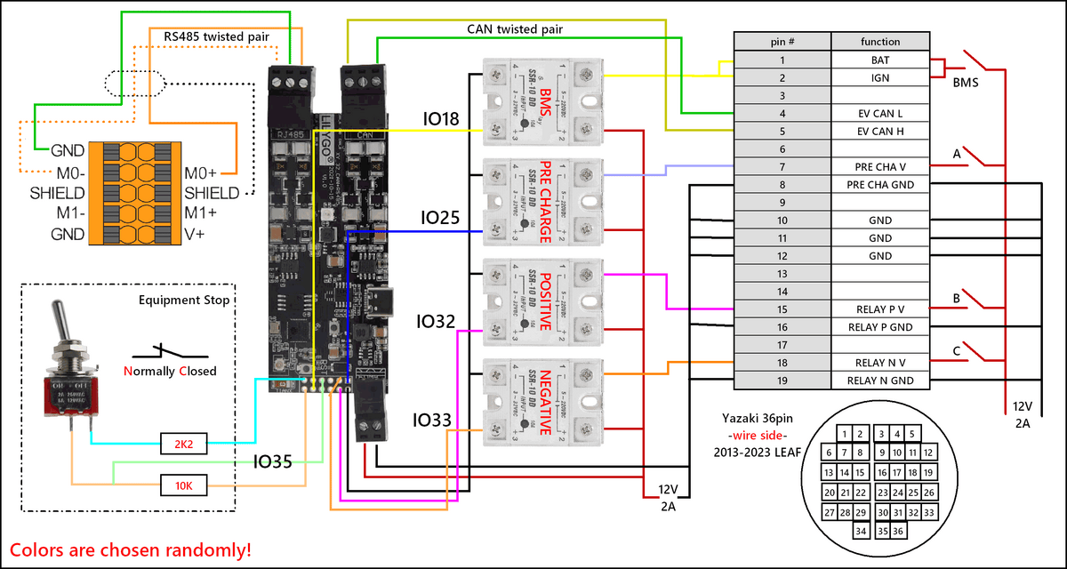 Nissan's own documentation uses pin numbering on the 36pin low voltage connector which does not match the moulded connector on AZE0/ZE1. The connections on this diagram have been renumbered so that they do. Scroll further down for the pinout of the 22pin connector for ZE0.
TIP
Check out our Low Voltage wiring page on how to make the connections in practice.
Automatic control 🤖~
Battery Emulator hardware can act on its own, and turn on/off the contactors/precharge resistor when the battery says it is OK and turn off when not OK to proceed. This is done via the 3.3V digital output header that is located on the supported boards.
To enable the feature in the software, Enable the Contactor control via GPIO option on the Settings page.

To keep things simple and durable, it is recommended to use Solid State Relays (SSR). These can be activated directly with 3V from the Emulator GPIOs, and control large DC currents. Follow the schematic above to complete the circuit.
The pin numbers on the picture are the ones used on the LilyGo T-CAN485, check out the pinout table for each board, which pin is defined as contactor output.
TIP
If you use fast-switching SSR relays with the Battery-Emulator hardware, you can also enable PWM mode for reduced power consumption. Here are parameters confirmed working with the LEAF contactors+PWM:

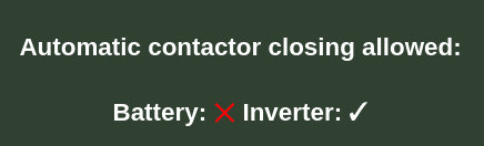
Before the contactors turn on, both Inverter and Battery needs to give OK ✅ signal. This can be verified via the Webinterface:
WARNING
New hardware requirement for Fronius  Battery voltage is reported towards Fronius inverters only after contactors are engaged. This means that old legacy installs using manual A/B/C switches for turning on battery contactors will no longer function with Fronius inverters. Only automatically controlled contactors via GPIO will work. This is a new stricter safety requirement to get the Fronius inverter to startup faster and with less errors. The bonus is that GPIO controlled contactors is inherently safer than manual A/B/C triggering.
Periodic restart of BMS~
The BMS in the Nissan LEAF packs was not designed originally to operate 24/7 under all conditions. Over time the SOC% will become less accurate, and in some conditions even the GIDS (Wh remaining) become confused (see Issue 86). BAT pin can be under +12V continuously, IGN pin should be the one turned off from time to time (as the wiring diagram above shows).
See the Periodic Reset page for details. Set Periodic BMS reset off time to 120 seconds for Nissan LEAF packs. Based on empiric observations the 30kWh (2013–2017, AZE0) pack benefits most from the 24h period together with the Skip reset for one period if balancing option enabled. Changing BMS starting sequence request to normal charge may improve balancing on packs that are in good shape (small cell voltage delta over the entire SOC range you use).
TIP
The LEAF BMS uses passive balancing: each of the 96 cells has a small resistor (shunt) that can be switched on to burn off a little energy as heat, slowly bringing fuller cells down to the level of the lowest ones. At the start of a balancing cycle it measures all cells and flags every cell sitting more than a small tolerance above the lowest one. While draining, it keeps count of how much it has taken from each flagged cell, and switches that cell's shunt off once the count says it is close enough to the lowest one. So a small difference between cells is normal, and the flagged cells aren't always the ones with the highest voltage at that moment. The target cell delta is around 17mV.
The same cells may stay flagged for many hours (sometimes a day) before draining really starts: the Cellmonitor shows them as cyan bars marked Pending, then Balancing while the list keeps changing, until it's empty. A BMS reset discards the progress and restarts the whole process, waiting included - which is why the Skip reset for one period if balancing option helps.
More Battery Info 📜~
The More Battery Info button at the bottom of the main page will open a window containing some extra information about the pack. A few notes about the most important ones:
- +12V BAT level: the voltage level of the 12V source that you use to power up the pack (at BAT and IGN inputs). Should not go under 10V!
- Insulation: insulation resistance measured by the BMS. When contactors are closed, this values averages around 100kΩ (may depend on inverter). When contactors are open, this shows much higher values. Both are normal like this. This value should not be considered, it's the inverter who decides if there's an insulation problem or not.
- Capacity as new: is the estimated capacity in kWh, when the pack was new out of the factory.
- Actual capacity: is the degraded capacity in Ah (and multiplied by the pack's nominal voltage in kWh) corresponding to the BMS's health knowledge about the cells.
- SOH raw: the raw State-Of-Health (and the average one) reported by the BMS on the CAN bus. The average one is what you'd see in LeafSpy. Both show 100% if the pack has been SOH-resetted recently.
- Hx: is a Nissan-specific measurement value related to the internal resistance of the pack. Shows 100% if the pack has been SOH-resetted recently (see further down below).
- QC charge count: the total number of quick (DC/Chademo) charges that have been started while the pack was operating in the car.
- AC charge count: the number of AC charges that have been started while in the car. This number increases at each pack boot and BMS reset when BMS starting sequence request is set to normal charge.
- Charge to full count: the number of charges that resulted in full battery.
- Turtle count: the number of cases when the car has been forced to run into turtle mode, to prevent over-discharging.
- lifetime usage histograms: Each event recorded the temperature at its start and the peak it reached. Peak (the hottest the pack got) drives the heat assessment; start temperature is shown alongside.
NOTE
The SOH value you see in Battery Emulator's main page is calculated from Capacity as new and Actual capacity. It may be slightly different from the (raw) SOH value you'd see in LeafSpy, but it's a relevant value even in case of a SOH-resetted pack, which would stick to 100% for a longer period of time.
A certain difference between total charges and the AC + QC counts is normal — it can happen when charging is interrupted (e.g. a power cut).
TIP
The LEAF battery is fully charged at 92-96% SOC. Use the Rescale SOC function to get a nicer looking 100% curve! However, Nissan specifically advises against habitual full charging, which adds wear - thus, for longer lifetime, you should set SOC max percentage to 80 on long term (during the summer, when the pack would charge to 100% quickly, and then would stay full almost all day).
Part numbers for Nissan LEAF batteries~
In case your battery is missing some wires/disconnect switches, here are the OEM part numbers and purchase links. Do note that it might be cheaper to source from your local scrapyard!
| Product | Purchase Link |
|---|---|
| Service disconnect switch (2011-2012) 2971C13NA0B | Ebay |
| Service disconnect switch (2013-2023) 297C1-3NF0A | Ebay |
| 22pin battery connector (2011-2012) Yazaki 7283-8750-30 | AliExpress |
| 36pin battery connector (2013-2023) Yazaki 7287-1065-30 | AliExpress |
| Precrimped 22/36 connectors | AliExpress |
| High voltage connector 80kW 297A6-5SH1A | Ebay |
| High voltage connector 80kW 297A22581R ZOE, also works | Ebay |
| High voltage 80kW cable 297A21061R from ZOE41 (both ends have the good connector type) | Ebay |
| 4ch SSR on DIN rail. Make sure you get the DC-CN version! | AliExpress |
TIP
All e-NV200 packs are technically AZE0 / ZE1, so 2013+ parts fit for them!
A spreadsheet with parts and links for a Nissan 40kwh battery and 8kW inverter (30A fuses).
Incompatible cables~
When searching on eBay you may come across other cables in the Zoe which use a connector that is similar in appearance but is much smaller:
- Zoe HV Wiring Harness - PN: 240419193R
- Zoe HV Engine Bay Wiring Harness - PN: 240413370R
- 297A6 3NA0A does not fit, you have to cut a part of it to use the pins.
These will not connect to the Leaf battery terminals.
Alternative HV connectors~
Original part number for Nissan Leaf battery is 297A65SH1A but a cheaper alternative for battery HV connector can be found in scrapyards. Renault Zoe or Kangoo Batteries use the same connector as Leaf battery. 297A22581R is the part numbers for both car.
The connector used is an Aptiv HV RCS 800.
Control wiring specifics~
The battery contactors drain continuously 0.4A each one at 12V. 0.5mm² (AWG 22) is enough cable section required current.
If you pin the connector yourself~
The Yazaki 22/36pin connectors are designed with an hole of 2.1mm that would contain cable and included elastic ring for water proof sealing. Normal cable of the above cross-section has protective insulation that is too thick (usually 2.1mm external diameter) to be used with the water proof seals. You may want to choose automotive cable that follow the reduced rubber cable standard (FLRY-A or B ISO 6722) that shouldn't be thicker than 1.5/1.7mm (better 1.5) outside diameter. Need at least 0.7/1mm thick cable (e.g. cable + wrap) to allow correct water proofing e.g. no ethernet cable can be used because it's too thin.
BTW it's not strictly necessary to be automotive grade cable if it has enough copper diameter (0.5mm²) and outer diameter of ~1.5mm.
NOTE
Ensure the pins go all the way to the bottom and the pin is seated properly with a "tick". If they are inserted incorrectly (not far enough, "wonky") then you won't have proper connection.
Of course if you install the battery indoors, you can omit the sealing rings and your wire choices are wider. You can use a 3D printed cover to protect the connector from falling debris.
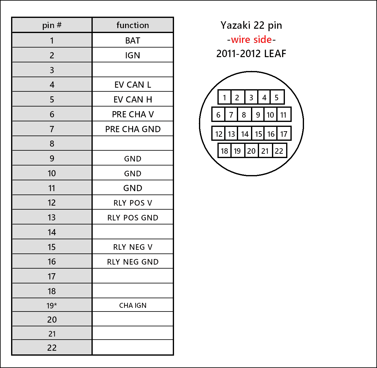
Pinout for the Yazaki 22pin connector, to be used with ZE0 packs:
Here is a nice example of a completed 22-pin 2011-2012 cable:
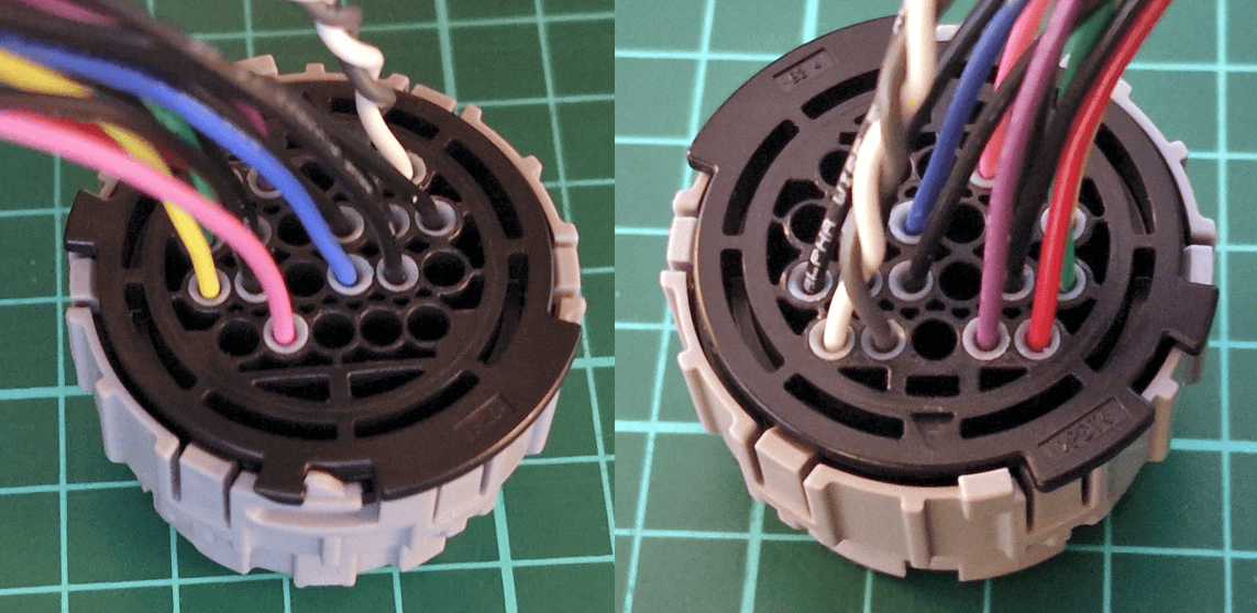
Crimping a 36pin connector:
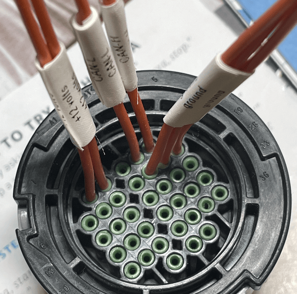
3D-printable parts~
You can print your own safety cover for the unused heater port, a dust protector for the LV connector and a fixation ring, even a complete Service Disconnect Switch or even your own HV Connector. Check out the 3D‐printable parts page.
Notes on stuck SOH ❤️🩹~
The 2016-2017 30kWh LEAF battery had a software bug in the BMS that caused the amount of kWh reported by the battery to be incorrect, and the state of health % to drop too fast. If you have one of these batteries, and it shows below 50% SOH, your battery might be affected. The Battery-Emulator can perform a degradation reset, and bring the Hx and SOH percentages reported by the BMS back up to 100%. This can be accessed from the Webserver, via the "More battery info" page. By pressing the "Reset degradation data", the clear is performed.
This will not give you any more battery capacity, though if you've swapped a bad cell with a good cell a reset is required to make use of the new capacity. Actual capacity reported in Ah is not affected by the reset.
NOTE
Currently SOH and Hx reported by the BMS is not following over time the real degradation of the cells in stationary storage. They remain stuck at the values you had when you first installed the pack. If you perform the degradation reset, this will show as 100% and will be stuck at that. However, this will widen up the SOC range you can use your battery in, getting a few kWh of usable energy back, but you'll have to carefully set your limits manually as described further down below.
IMPORTANT
The degradation reset only works on 2011-2017 (ZE0/AZE0) batteries.
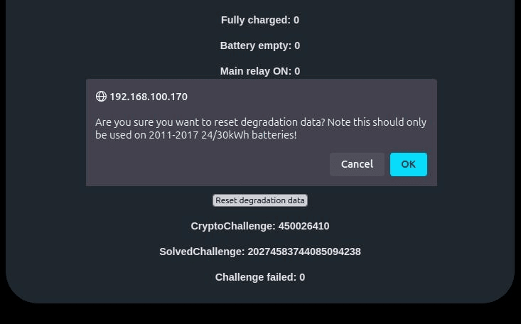
Performing the reset~
To perform a proper SOH% reset, that sticks between reboots, choose how to perform the following steps:
Remotely~
NOTE
You need Home Assistant set up to be able to do this remotely, by triggering a BMS Reset on demand.
Also, this can only be done remotely if only IGN is cut by BMS Reset and if the battery is alone on the CAN bus.
- Set Periodic BMS reset off time to 180 s
- Open contactors
- Reset battery degradation via the More Battery Info page
- Press Reset BMS in Home Assistant, and wait for the 180s to pass (watch Battery Emulator main page)
- Close contactors
- Reboot Battery Emulator
At the location~
- Open contactors
- Reset battery degradation via the More Battery Info page
- Disconnect CAN cable from the battery
- Keep BMS BAT power ON, only remove IGN 12V power
- Wait 3 minutes
- Reconnect CAN cables
- Restore 12V to IGN
- Close contactors
- Reboot Battery Emulator
After these steps, the CAN-reported SOH and Hx reset to 100% becomes persistent. Actual capacity in Ah is not affected by the reset.
Set your own, real limits~
Note that after you reset the SOH to 100%, the BMS will let charging and discharging the cells likely beyond the limits which are safe to use on long term, in respect to the longevity of the cells. In stationary usage the battery charges and discharges much slower, and in a different pattern than when it used to do in a car.
You can set up Home Assistant which lets you track cell voltages and delta on longer term, to be able to investigate the behavior.
To see some results, follow these steps after you do the reset (in normal ambient conditions, avoid extreme cold or hot periods):
- Disable Rescale SOC if you have it set
- Let the battery to discharge to empty
- Let the battery to charge to full
- Let the battery to discharge to empty again
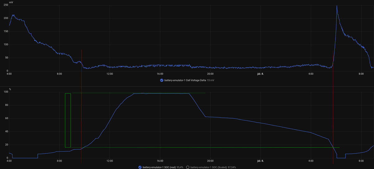
- Watch how the values of Cell Voltage Delta and SOC (real) change over time as approaching full and empty
For example:
TIP
The BMS will prevent damage to the cells when discharging to empty and charging to full. Battery Emulator will show these events as Battery is completely discharged and Battery is fully charged. You'll likely see Large cell voltage deviation! Check balancing of cells too. The goal is to find the thresholds you can manually set between which the battery can operate without running into these regularly.
Try to find the widest time area of Cell Voltage Delta where the value changes least - that's the most comfortable and safe "zone" for the cells to operate. Look at the SOH graph in the same time period - that should give you the min and the max percentage of SOC rescaling you can set in Battery Emulator, to prevent the battery to go in the high cell voltage delta zone. Take into account the absolute minimum SOC value your inverter is willing to go until (eg. Fronius allows discharging to 5% only, doesn't go below), you can reduce min SOC rescale about by that amount.
In the example above, the top graph establishes the red lines, which show the comfortable area of Cell Voltage Delta. The green lines show where the SOC curve intersects the red lines: this gives the min and the max SOC rescale values for a safe zone. (note the slight hysteresis between charge and discharge, take the highest value for safety).
This way you'll still be in the safe zone with your battery, but you'll likely be able to use bigger capacity than the original SOH allowed in the BMS before reset. Re-evaluate this graph periodically, every 3 months (no need to do full charge-discharge so often, just keep your eye on Cell Voltage Delta and SOC (real) relation on normal usage)
Physical size 📏~
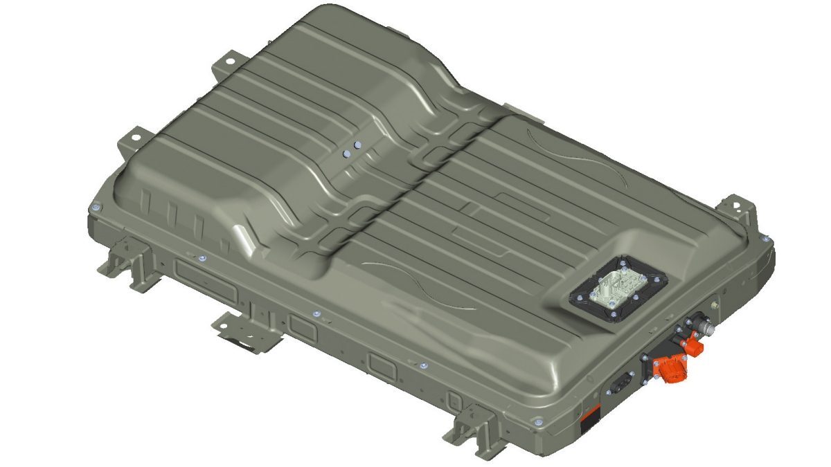
The Leaf battery packs (24/30/40kWh) are all the same physical size. The 62kWh battery however is 40mm taller.
- 24kWh (2011–2012, ZE0) = 277kg (601lb) 1547.0 (L) × 1188.0 (W) × 264.0 (H) mm
- 30kWh (2013–2017, AZE0) = 294kg (648lb) 1547.0 (L) × 1188.0 (W) × 264.0 (H) mm
- 40kWh (2018–2023, ZE1) = 303kg (668lb) 1547.0 (L) × 1188.0 (W) × 264.0 (H) mm
- 62kWh (2018–2023, ZE1) = 410kg (903lb) 1547.0 (L) × 1188.0 (W) × 304.0 (H) mm
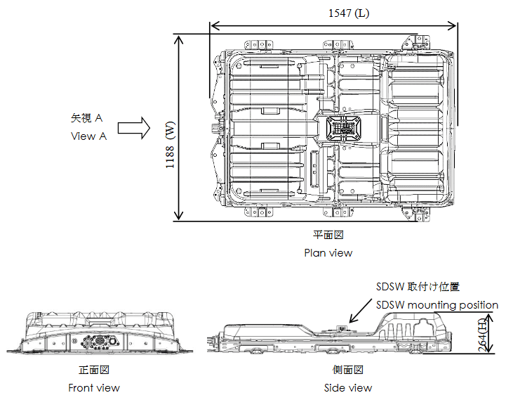
The e-NV200 battery pack is 1578 (L) x 1102 (W) x 266 (H) mm and is packaged differently from the Leaf packs (active cooling and service disconnect at front instead of middle).
Test before you buy 🔍~
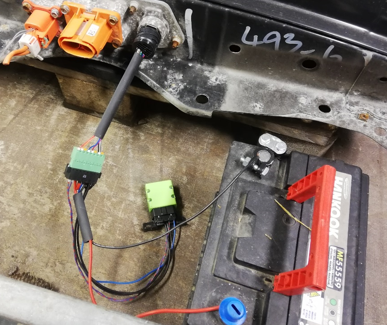
You can test on-site a Leaf pack before you buy it, if you make a portable cable with a Yazaki connector and take a 12V battery (lead acid or 3x18650 in series) with you. If you have a spare, compatible ESP32 board with CAN connector, you can use Battery Emulator with no inverter configured to start talking with the pack, open Cell monitor or More Battery Info and check health and lifetime usage. Worth making a rig with SSRs and enable Contactor control via GPIO / Periodic BMS reset settings, so the contactors would close to verify them with a multimeter that the pack properly outputs the voltage.
You can even connect LeafSpy the same way, if you get an OBD2 socket hooked to the Yazaki connector:
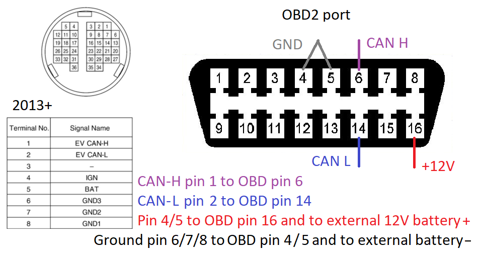
These pictures show it for AZE0/ZE1. For the ZE0 2011-2012 it's similar, you just need to use the other Yazaki connector, with different pin locations (see above for pinout).
⚠️ To ensure you don't deal with an insulation-faulted pack, measure DC voltage between each contact of the service disconnect switch and the case (do this with the pack completely powered off and disconnected from anything). You should see a DC voltage slowly decreasing to 0 (wait till it decreases close to 0 from both). If you'd see a constant voltage standing still between the battery casing and any of the contacts, that pack likely has an insulation fault and may be dangerous to use!
CAUTION
Working with high voltage is dangerous. Always follow local laws and regulations regarding high voltage work. If you are unsure about the rules in your country, consult a licensed electrician for more information.