Stark CMR
MCU / flash: ESP32 (Xtensa LX6 dual-core, 240 MHz); 4 MB flash on CMR v1, 8 MB on v2.
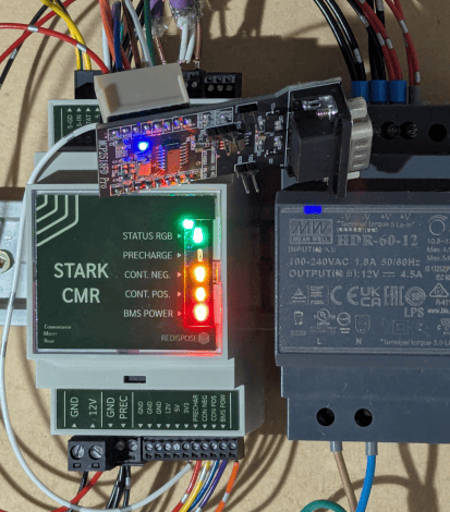
The Stark CMR (SCMR) is a commercially available and CE certified product specifically designed for the Battery Emulator project. It aims to make installs clean, easy, expandable and electrician friendly.
Get the SCMR and other related hardware via the official web shop.
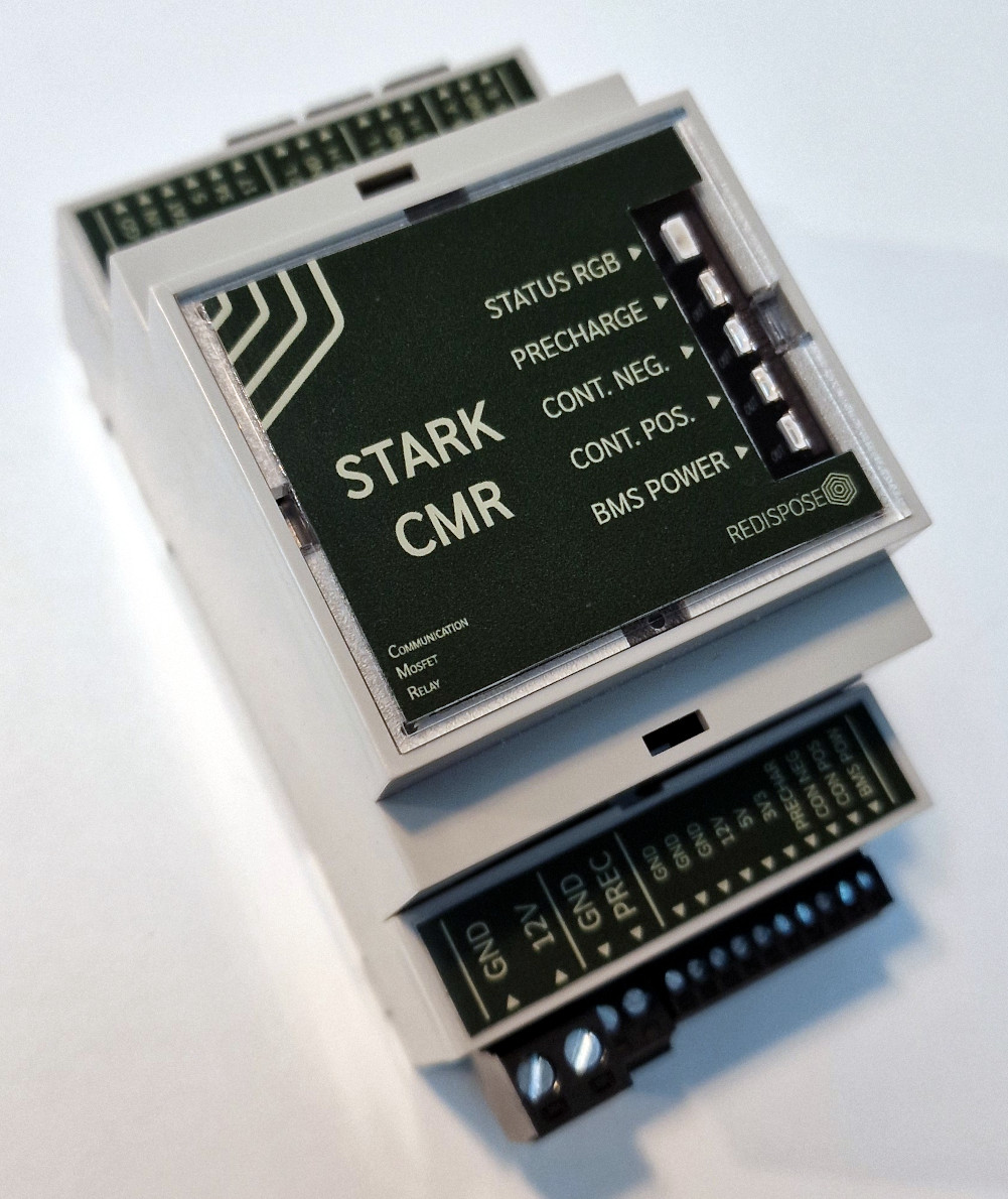
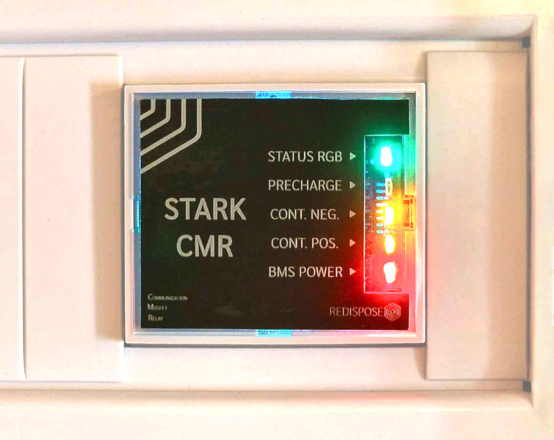
Overview of features~
| GPIO | Function |
|---|---|
| 0 | FLA push-button — long-press options available |
| 2 | Equipment stop input — or SMA inverter contactor enable input (also broken out on the extra header) |
| 4 | LED chain data: pixel 0 = status LED, pixels 1–4 = precharge, negative contactor, positive contactor, BMS Power |
| 5 | On-board MCP2518FD SDI |
| 12 | Second MCP2518FD (GPIO header add-on): CS — JTAG TDI on the header |
| 14 | Second MCP2518FD (GPIO header add-on): INT — JTAG TMS on the header |
| 15 | Third battery contactors output — JTAG TDO on the header |
| 16 | On-board MCP2518FD SCK on Stark CMR v1 (4 MB flash) |
| 17 | On-board MCP2518FD SCK on Stark CMR v2 (also available on the extra header when CAN channel 2 is inactive) |
| 18 | On-board MCP2518FD CS |
| 19 | Second battery contactors output — or HIA4V1 precharge control (also on the extra header) |
| 21 | RS485 RX |
| 22 | RS485 TX |
| 23 | BMS Power output (default 23) — or precharge contactor output (when BMS Power moves to Pin 25) |
| 25 | Precharge contactor output (default) — or BMS Power output — or inverter disconnect contactor output — or battery wake-up 1 (WUP1); held across a reset/OTA reboot |
| 26 | Native CAN RX |
| 27 | Native CAN TX |
| 32 | Positive contactor output — or battery wake-up 2 (WUP2) |
| 33 | Negative contactor output |
| 34 | On-board MCP2518FD SDO |
| 35 | On-board MCP2518FD INT |
NOTE
BMS Power is always enabled on this board (always_enable_bms_power()).
Power~
Supply voltage (+5VDC - +16VDC) protected with reverse polarity circuitry
Operating current < 300mA @ 3,3VDC when all outputs are activated
USB connection and simultaneous external power supply are compatible
All 3V3 logic with resettable over-current protection
Four individually controllable power outputs, equal to the DC input voltage consisting of:
- 1 relay channel, 7A continuous, 12A maximum. Located on the main output 1 connector.
- 3 MOSFET channels, 0,65A continuous, 1,4A maximum with resettable over-current protection.
The MOSFET channels are located on the secondary output connector.
Current specifications are valid at a surrounding temperature of 25°C or below.
Communication~
- 1 x RS485 channel using Texas Instruments transceiver
- 1 x CAN channel using Texas Instruments transceiver
- 1 x CAN/CAN-FD channel using Microchip technology MCP2518FD controller and Texas Instruments transceiver
All of the above protected using GDT/ESD/TVS discrete components
Easily accessible DIP switches for termination on all three lines
SoC~
ESP32-WROOM-32E using ESP32-D0WDR2-V3
Xtensa® dual-core 32-bit LX6 microprocessor, up to 240 MHz
448 KB ROM, 520 KB SRAM, 16 KB SRAM in RTC
Equipped with 8MB Flash and 2MB PSRAM
Status LEDs~
- 1 x logic power indicator (Blue)
- 4 x outputs status indicators (Green: GPIO 25, Yellow: GPIO 33, Orange: GPIO 32, Red: GPIO 23)
- 1 x programmable REG WS2812B (GPIO 4)
All except power indicator available on board as well as on perpendicular plug-in PCB for better visibility
Extra headers~
7 available GPIOs (5 freely usable, 1 bootstrapped, 1 conditioned)
SPI/JTAG header (or used as part of the 6 GPIOs)
Maximum current per GPIO must not exceed 20mA
Physical control / Interaction~
- 1 x USB-C power and data connector
- 3 x DIP-switches toggling individual termination resistors for RS585, CAN and CAN/CAN-FD
- 2 x Momentary switches for SoC manual reset and flash (GPIO-0 to GND) functions
- 1 x JTAG header
Where can I get one?~
Additional information on the Stark CMR and upcoming related products is available at shop.redispo.se where you also have the option to buy the unit
On the project discord you'll find a thread called "Stark Hardware" where you can chat to Stark CMR users.<br/
You're also welcome to contact Johan directly if you have any questions regarding the hardware.
Documents~
Latest instruction manual SCMR01
Latest instruction manual SCMR02
Installing the software~
Follow the quickstart guide to install the Battery-Emulator software onto the board for the initial setup.
Over the air (OTA) software updates~
When updating this board OTA, be sure to select the software marked for this board. The files will be marked like this, signaling that this is Stark hardware.
BE_vX.Y.Z_StarkCMR.ota.bin
Interfaces~
The board comes with 2 CAN channels, the second one of them being capable of CAN-FD. The board also has an RS485 channel, which can be used for Modbus inverters or RS485 batteries.
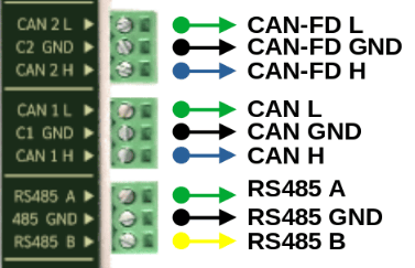
The interfaces correspond to the following options in the Battery-Emulator software
-
CAN-1 -> Native CAN
- CAN 1L (CAN-LOW)
- CAN 1H (CAN-HIGH)
-
CAN-2 -> Native CAN FD
- CAN 2L (CAN-LOW)
- CAN 2H (CAN-HIGH)
- Note, this channel can be used as classic CAN by enabling "Use CanFD as classic CAN" option
-
RS485 -> RS485 / Modbus
- RS485 A
- RS485 B
Adding a third CAN channel~
For integrations that need double/triple battery compatibility via CAN, or an additional CAN-FD chanel, you can add an MCP2518FD add-on board via the GPIO expansion header. Connect the wires as following:
- IMT to 14
- CS to 12
- SCK to 17
- MISO to 34
- MOSI to 5
- 3.3V to 3.3V
- 5V to 5V
- GND to GND
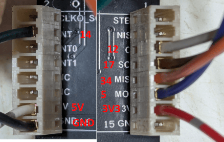
After connecting the board, you can enable the add-on CAN by configuring it as MCP2518FD (GPIO add-on) to component.
Example, Stark CMR used to control 3x separate Nissan LEAF batteries with one of them being on an add-on MCP2518FD board
Example connection diagram~
This is an example wiring diagram for connecting the Stark CRM, a Nissan Leaf battery pack, a Fronius inverter and an E-stop button (NC). This diagram shows high side switching contactors which is found in most battery packs. I.e. +12V is "fed into" the battery on the dedicated pins to close the contactors.
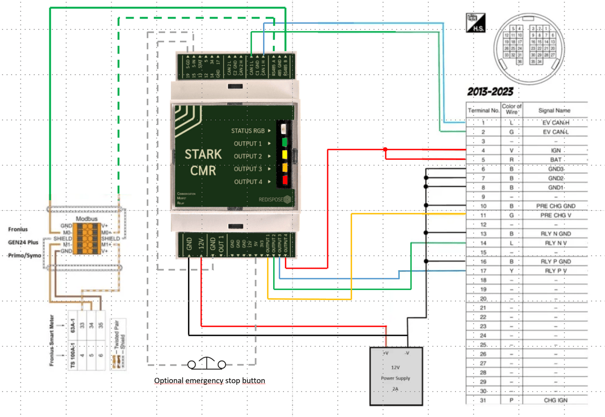
Notes: All connections marked GND on the SCMR are joined via the GND plane of the PCB. 5V is the suggested voltage level for the E-stop in this case but it will also work using 12V or 3.3V.
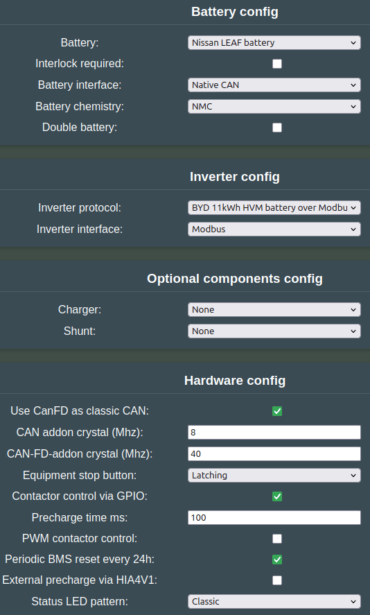
The configuration for the above example would look like this:
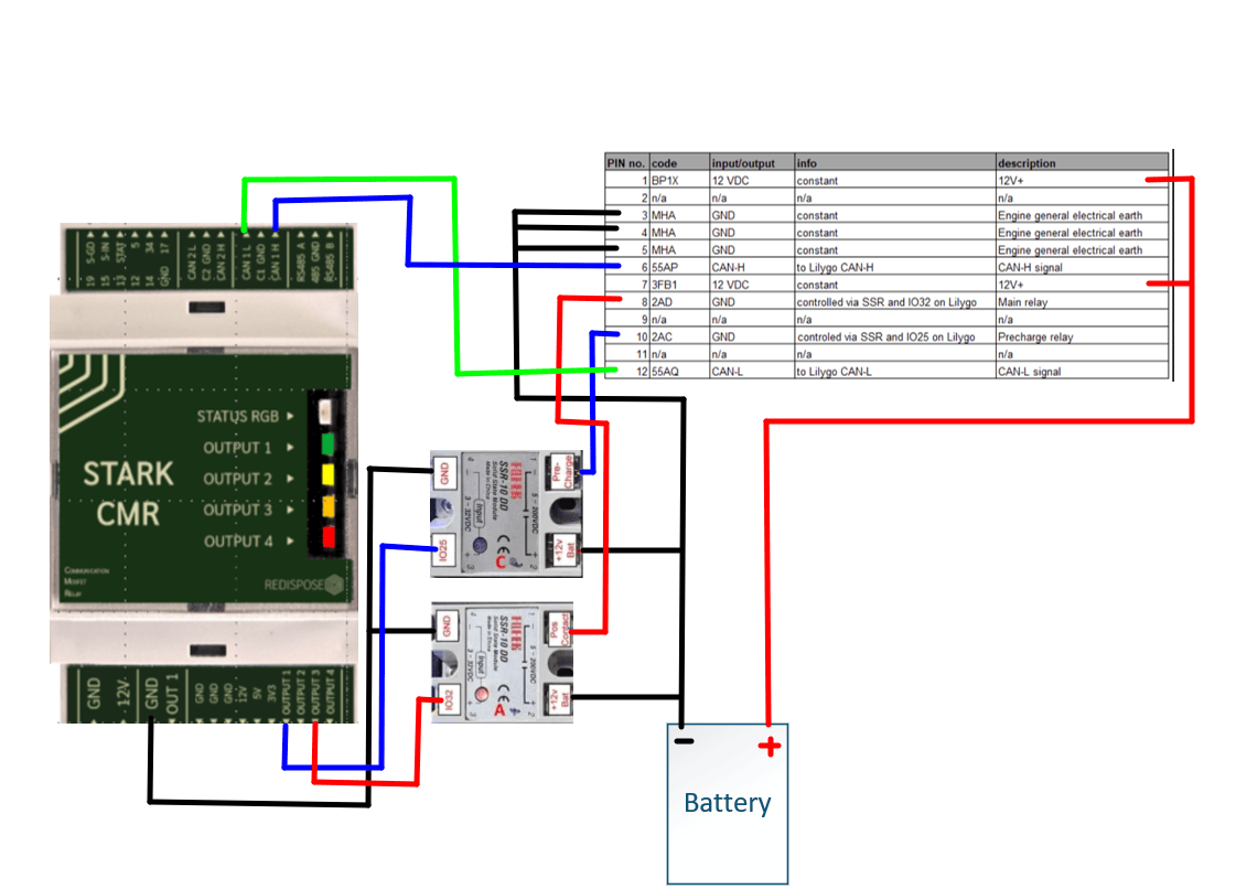
The next wiring diagram shows an example for wiring a Renault Zoe battery. This differs from the previous example as the contactors use low side switching, i.e. the contactors will be closed when the dedicated pins from the contactors on the battery are "shorted to ground".
See also~
- BOOT button for special features to enable AP, wipe wifi settings or factory reset the device
- CAN add-on MCP2518FD for an additional CAN interface
CAUTION
Working with high voltage is dangerous. Always follow local laws and regulations regarding high voltage work. If you are unsure about the rules in your country, consult a licensed electrician for more information.