Ampera‐e 64 kWh
GM BEV2 platform~
The 60-66kWh battery in the GM BEV2 platform can be found in the following vehicles.
- Opel Ampera-E (2017-2021)
- Chevrolet Bolt (2016-2023)
2020+ models are 64 KWh, earlier are 57 kWh.
Software configuration~
For this battery type, use the option called "Chevrolet Bolt EV/Opel Ampera-E" under the "Battery Protocol" setting.
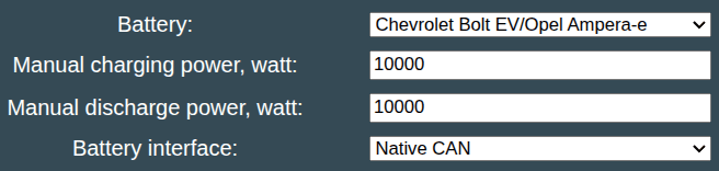
Also remember to configure the allowed charging power, since we do not read this value via CAN.
The battery uses 12V controlled contactors, so use Contactor Control via GPIO if you want Battery-Emulator to also control the contactors via GPIO.

One user reported using 3xf this type of relay with the LilyGo hardware.
Wiring diagrams~
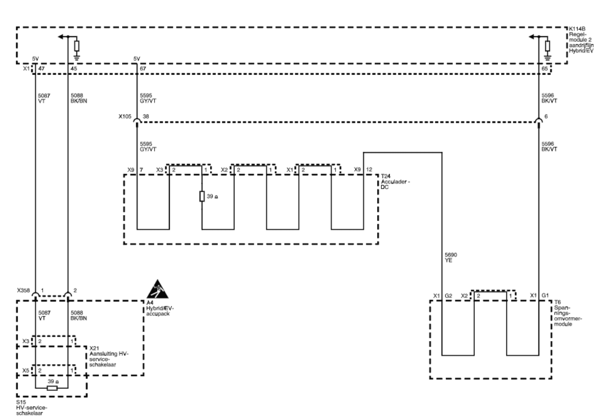
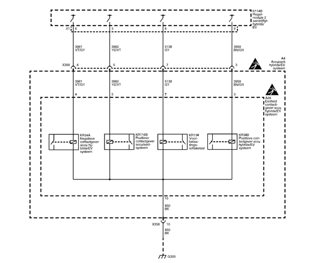
Connect the low voltage wiring like this:
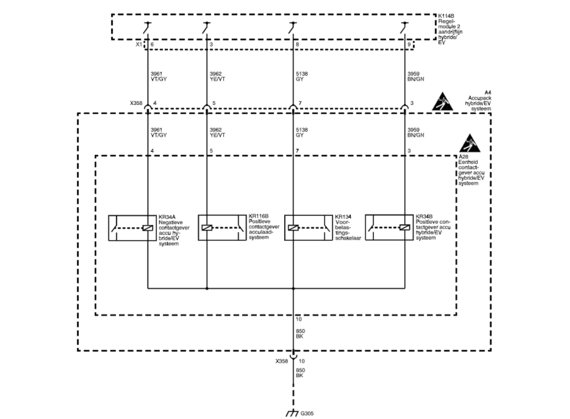
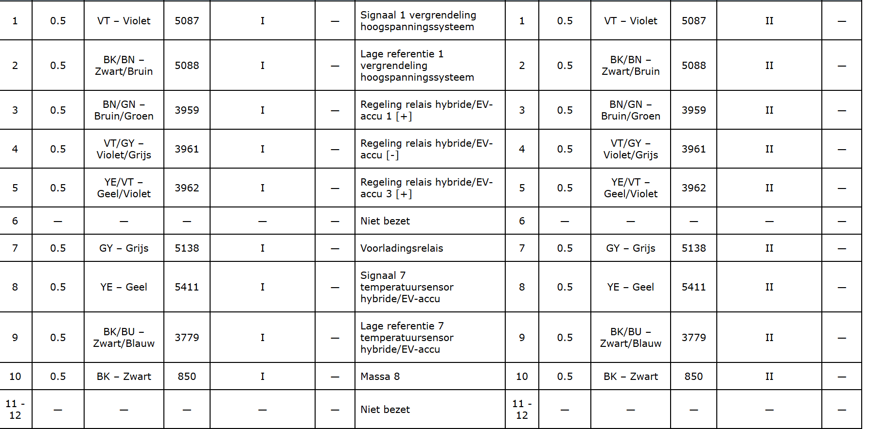
X358 connector (black)
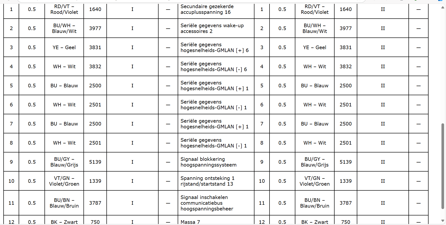
- Pin 1 & 2 should be grounded (if pin 1 has 5V we lock the battery?)
- Pin 3 12v+ positive contactor
- Pin 4 12v+ negative contactor
- Pin 5 12v+ positive contactor for aux connector
- Pin 7 12v+ precharge
- Pin 8 is coolant temp, pin 9 is ref. to pin 8.
- Pin 10 to ground
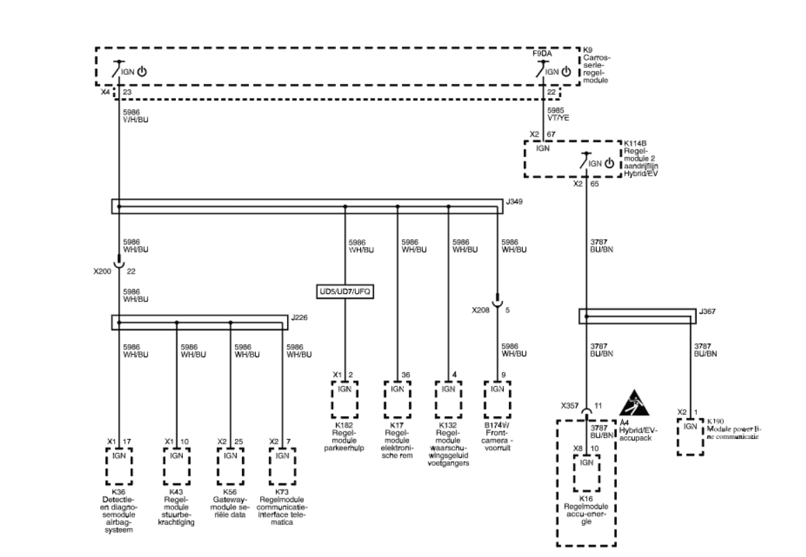
X357 connector (gray)
- Pin 1 fused with 10A (+12V)
- Pin 2 we wake up the sensors (+12V)
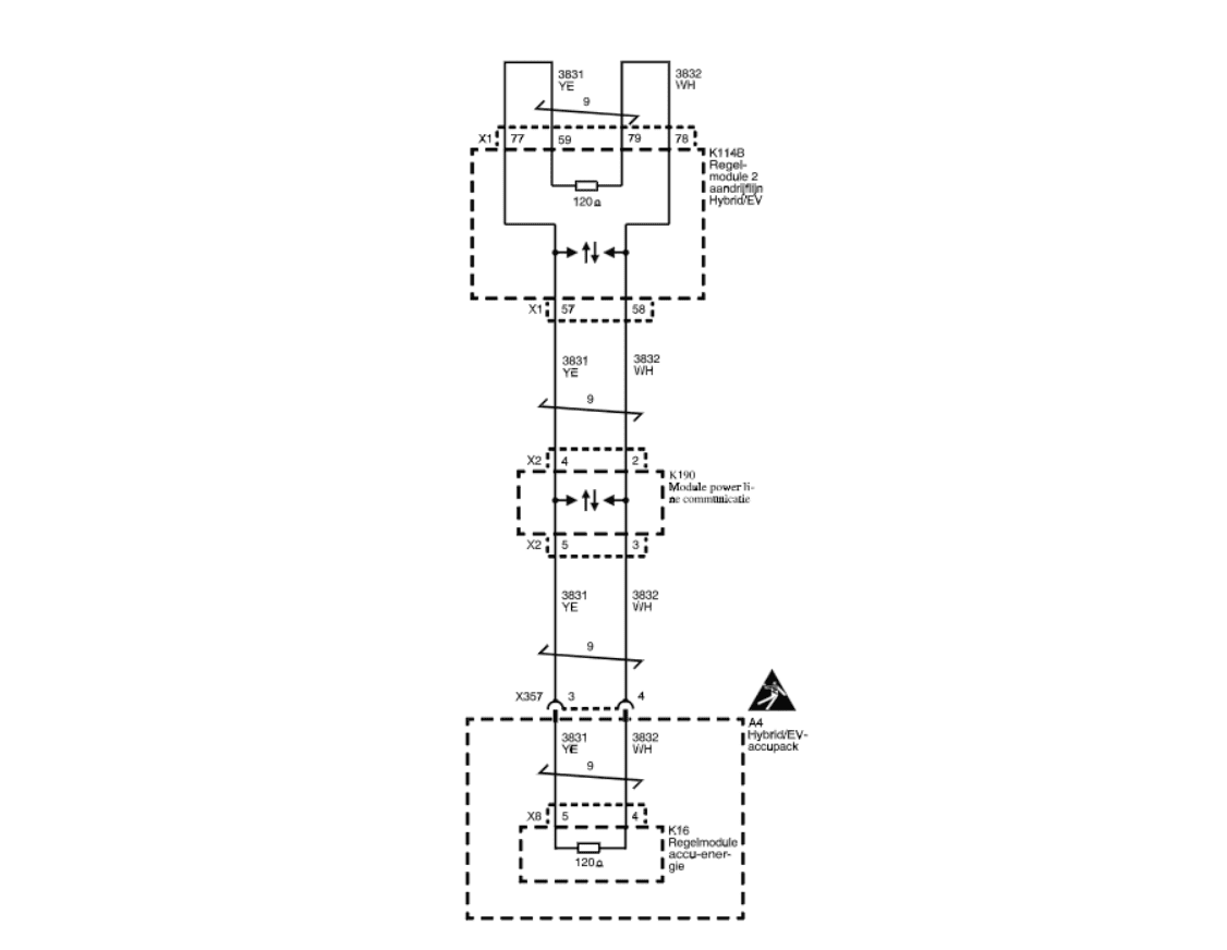
- Pin 3 & 4 relevant CAN H/L (?)
- Pin 5 & 6 relevant CAN H/L (?)
- Pin 7 & 8 relevant CAN H/L (?)
- Pin 9 is blocking ignition if we feed 5V
- Pin 10 wake up BMS (+12V)
- Pin 11 wake up communication (+12V)
- Pin 12 to ground
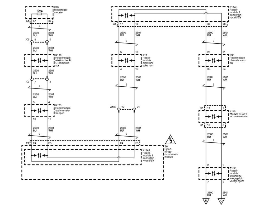
All three CAN's should be connected to BE device.
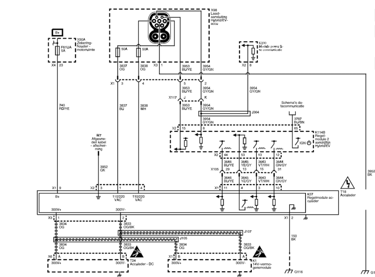
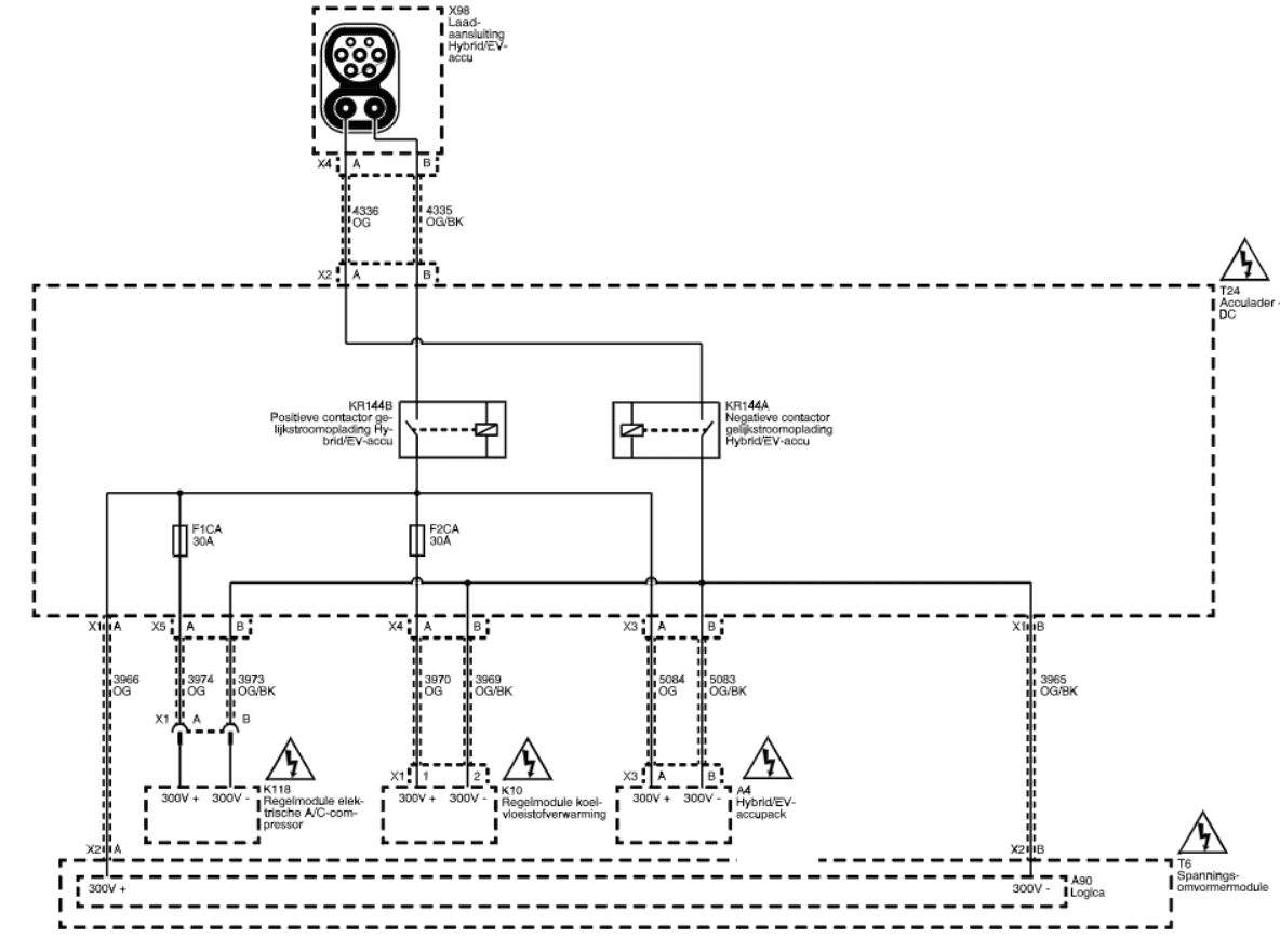
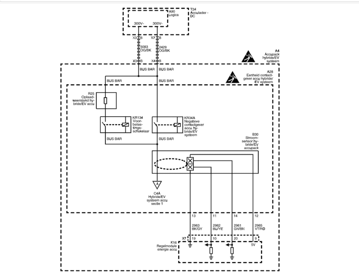
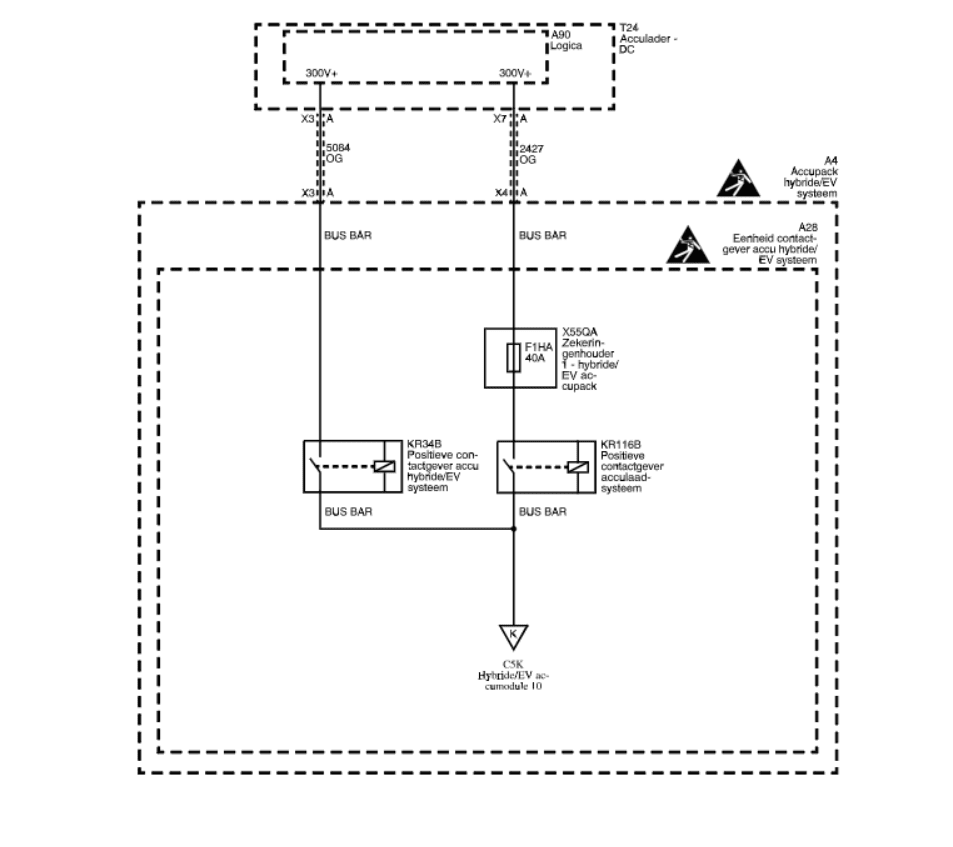
The following diagrams will help you to connect to the CAN buses on the Opel/Chevy batteries:
NOTE
These batteries have multiple CAN buses that needs to be jumpered together to form one large CAN bus the resistor on the board must be removed.
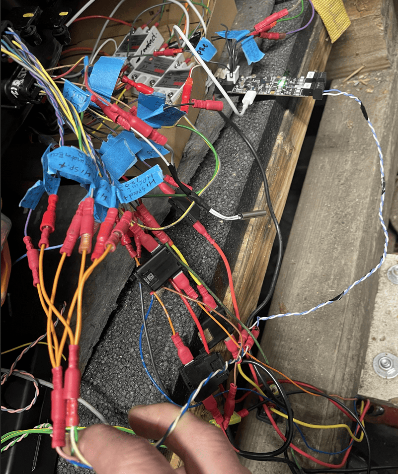
Example, development environment with contactor control via GPIO, and all 3x CAN buses connected together as one single bus
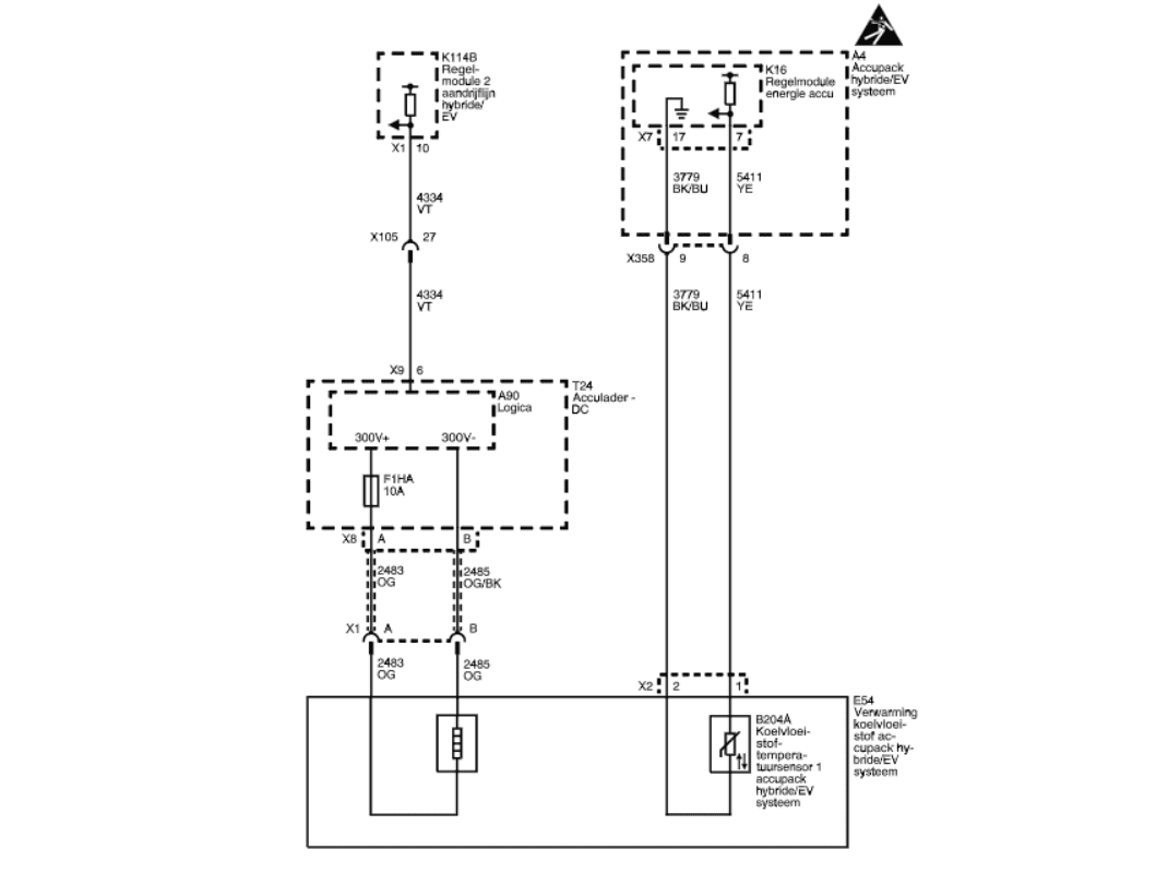
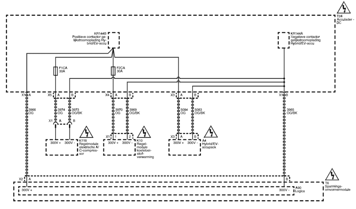
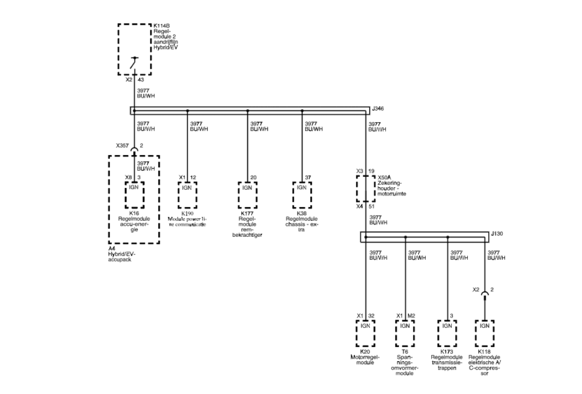
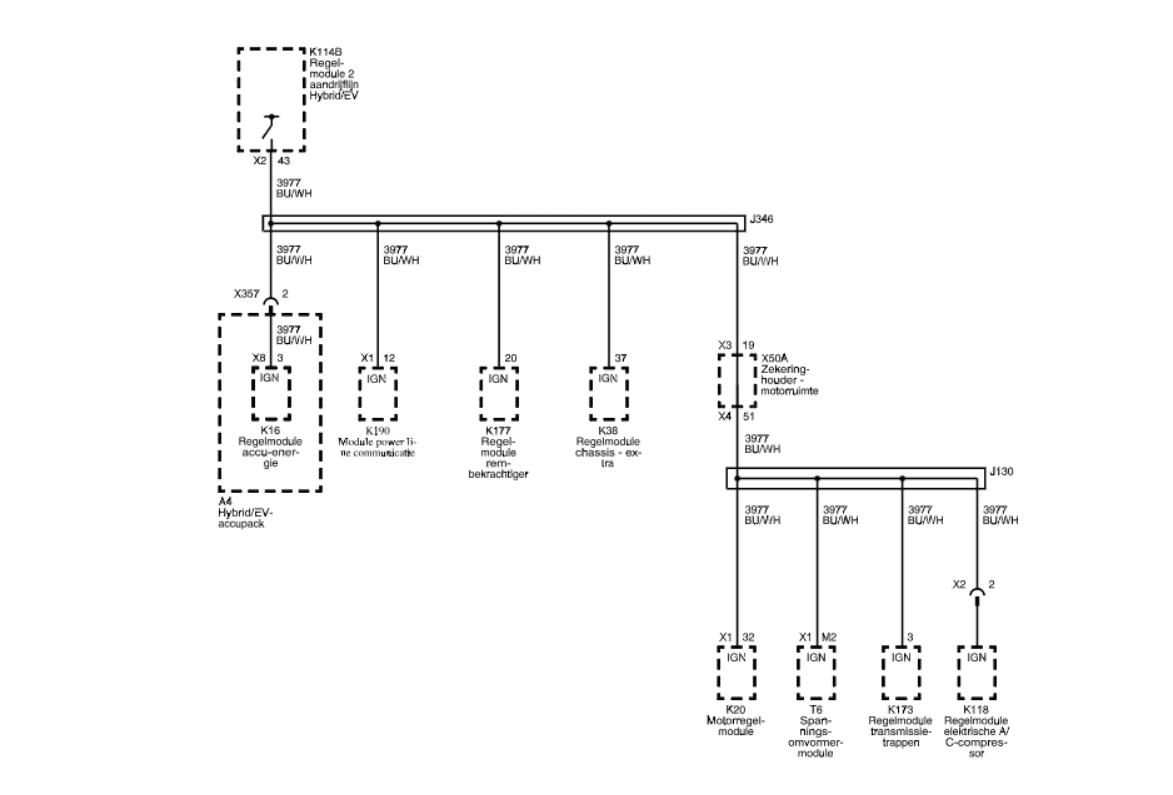
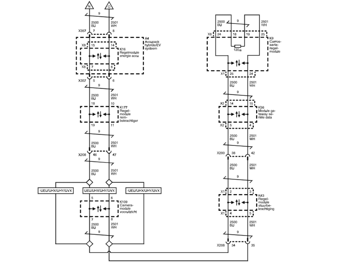
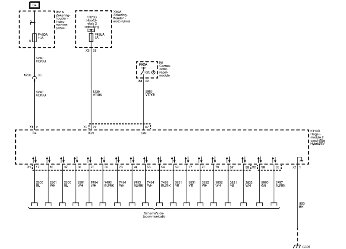
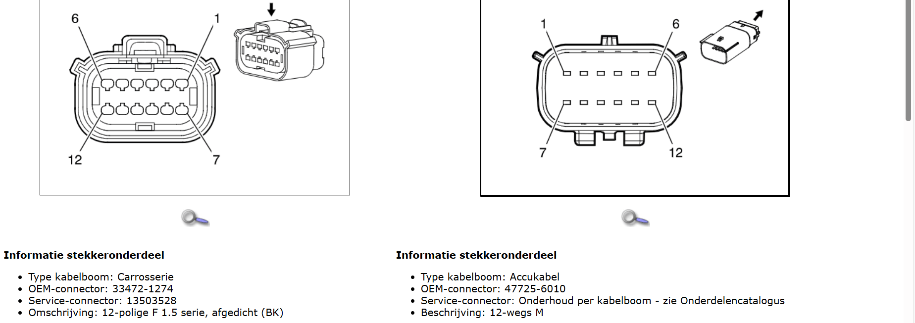
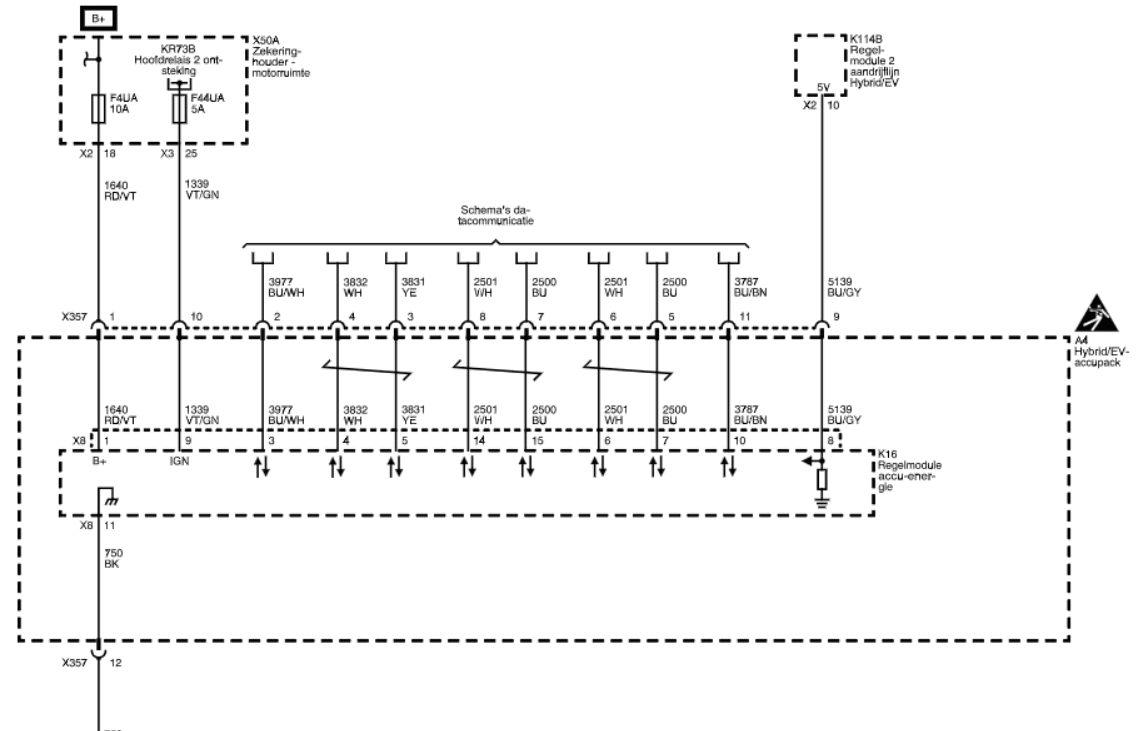 Connector X357 OEM 33472-1259 Service Connector 19333239
- X357
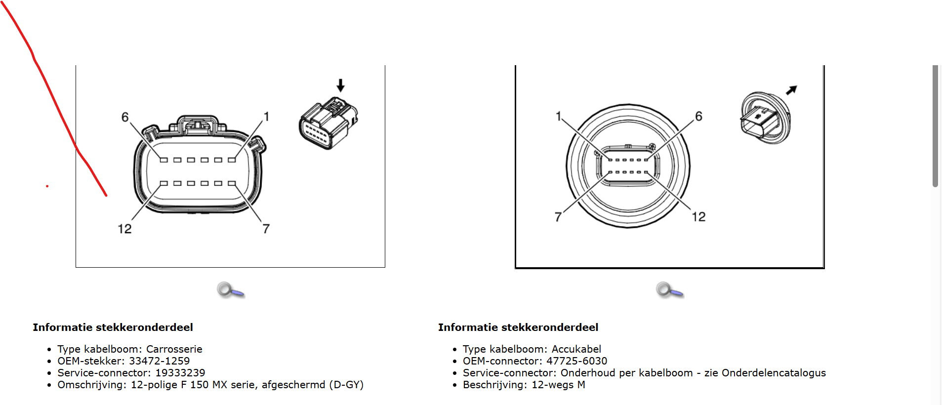
X358
I had connectors but these fit also, one needs to modify by yourself.
Disconnect switch 24281696 24288304 24291219 or latest part number 24294004
Contactors must be connected with the emulator via the GPIO pins: Contactor control via GPIO pins
Please note that the precharge contactor is placed in the negative line of battery. To make precharge work the positive contactor must close before precharge contactor. Workaround: Swap Positive and negative control-lines to relays.
CAUTION
Working with high voltage is dangerous. Always follow local laws and regulations regarding high voltage work. If you are unsure about the rules in your country, consult a licensed electrician for more information.