Double Battery
What is this feature?~
Double Battery means running two battery packs at the same time. This doubles the capacity of the system. In case you need more energy than one EV pack can provide, this functionality is for you.
Good info on running multiple packs and associated risks: orionbms
If you need more capacity than Double Battery provides, you can also go Triple Battery.
How does parallel operation work?~
The batteries get connected in parallel. This means the voltage stays the same, but the capacity doubles.
IMPORTANT
The batteries need to be of the same model and size, and preferably as close as possible in state of health. Do not connect battery packs with too much variation in condition, this lowers overall efficiency significantly!
CAUTION
Do not connect packs in series!
- How to ensure balancing, that each battery reaches 100%? In parallel operation this is easy, in series it's next to impossible.
- There are no safeties implemented for operation in series connection! No control over CAN controlled contactors would make this feature hard to use safely.
- None of the isolation is designed for double the working voltage. Yes, each battery only sees it's own voltage, but the isolation to earth and in the BMS comms suddenly sees twice. As do any internal contactors, which is probably the more immediate issue.
Which inverters are compatible?~
Double-Battery can be run on all inverters. The inverter will think that there is just one large battery attached.
NOTE
Double-Battery should not be confused with Dual Input inverters. Dual input can have 2 separate batteries operating at the same time (Foxess or Sofar for instance). lookup how to in your inverter type/brand Wiki for more information about Dual input.
How the packs become one virtual battery~
Each battery pack keeps its own readings. Once per second Battery-Emulator combines them into a single virtual battery, and that is the only thing the inverter ever sees. On the web interface it's shown in a combined card on the main page; the cards below it show each pack on its own:
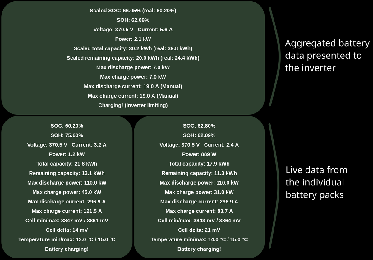
Not every value combines the same way. Some add up, some take the weakest pack, some take the extremes:
| Value | How the packs are combined | Why |
|---|---|---|
| Total capacity | Sum | Two 30 kWh packs present 60 kWh |
| Remaining capacity | Sum | |
| Lifetime charged / discharged energy | Sum | |
| Current | Sum | Each pack contributes its share of the load |
| Power | Combined current × DC bus voltage | |
| Voltage | The first pack's measurement | Packs are in parallel, so they share one bus voltage |
| SOC | The emptiest pack that is on the bus, blending towards the fullest once that one passes 90% | Discharge stops when the first pack empties, and charge tapers smoothly as the first pack fills, instead of jumping the moment one tops out |
| State of health | The lowest any pack reports | The installation is only as healthy as the pack that fails first |
| Cell voltage min / max | Lowest and highest found in any pack | |
| Temperature min / max | Lowest and highest found in any pack | |
| Charge / discharge voltage limits | Lowest ceiling and highest floor any pack reports | A mismatched pack is never asked to go past what it tolerates |
| Max charge power | The lowest any pack allows. With Parallel headroom tracking on, it starts there and is raised step by step to what the packs take together | See Parallel headroom tracking |
| Max discharge power | The lowest any pack allows — not the sum | See the warning below |
| Max charge / discharge current | Derived from the combined power limit at bus voltage, then capped by your charge/discharge settings |
Discharge power does not double
Capacity doubles, discharge power does not. The inverter is told the discharge limit of the weakest pack, because there is no way to steer current towards one pack and away from another — they share a bus and divide the current between themselves according to their own internal resistance. Reporting the sum would allow a healthy pack to drag a weak one past its limit.
So two packs that each allow 10 kW of discharge are presented as 10 kW, not 20 kW. If one pack drops to 6 kW, the whole installation drops to 6 kW.
Faults stop the whole installation
If any pack reports a fault, or the safety layer shuts one down, its limits go to zero — and since the combined limits start from the lowest of the packs, the inverter is told zero as well. One pack in trouble stops the system, not just itself.
Parallel headroom tracking~
For charging, the lowest pack limit is a cautious approach: the packs share whatever the inverter pushes, so two alike packs each take about half of it and neither ever reaches its own limit. With Parallel headroom tracking enabled, the charge limit only starts at the lowest pack limit, and is raised from there in steps while the inverter actually charges at it. When used with solar panels, this lets more of the available power into the batteries, especially in low-sun conditions when approaching fully charged state, where packs start applying input power limits. The tracker overbooks the total power so that individual battery powers still stay within, but as close as possible to their allowances.
It is off by default. Turn it on with Parallel headroom tracking in the Battery config card of the Settings page, which appears once at least Double battery is ticked, and reboot. Off, charging works like discharging: the inverter is told the lowest limit of all the packs.
How the raise works:
- Each step adds the headroom of the pack closest to its own limit: its limit minus the power it is measured to take. Every pack only takes its share of the extra, so a step of that size cannot push any pack past its limit.
- After every step the inverter gets 10 seconds to follow before the next one is measured, as some inverters only read the limits every few seconds (Fronius over Modbus every 5).
- There is no step while the inverter pushes less than 95% of what it is allowed — not enough sun, its own maximum, a current cap, the ramp or the taper holding it below — or while a pack on the bus shows no charge current.
- A step only counts on the lowest limit each pack has reported in the last 60 seconds, so a BMS that flips its limit between two values is not chased up and down. A higher limit counts once it has stayed up for a minute.
- When a pack's BMS lowers its limit, the combined limit is cut at once to the total that puts that pack on its new limit at the split the packs last took the full limit at, even while a cloud, a household load or the inverter's own maximum keeps the packs well below their limits. How the packs share a small current says little about how they will share a large one, so the split under a cloud is not used for this. A pack that goes over its limit because the split between the packs moved is cut back at once to the split measured at that moment. A pack already taking more than its new limit stays over it until the inverter reads the cut, a few seconds at most, the same as a single pack would.
- The limit never goes below the lowest pack limit, which it follows at once in both directions, nor above the sum of the packs' limits. It starts over from the lowest pack limit once charging has stopped for 5 minutes, when a pack leaves the bus, or when a pack allows no charge at all. A load the panels cannot cover for a while, like a kettle or a passing cloud, only pauses the raise: charging resumes where it was.
For example: two alike packs that each allow 3 kW end up charging in total at close to 6 kW, not just 3 kW. Packs that share the current unevenly settle where the one taking the larger share reaches its limit. The combined card shows the raised limit, the pack cards below it what each BMS allows.
Ramp up charge limits gradually and Charge power tapering based on SOC work on this combined limit, after the raise, so they always have the last word.
Every pack has to report its own current
The headroom comes from the current each pack's own BMS reports. A pack that reports none looks like a pack taking nothing, so it holds every step off, and the charge limit stays at the lowest pack limit. If a pack's current reading goes missing while the installation charges at a quarter of the combined limit or more, the next drop of that pack's limit takes the combined limit straight back to the lowest pack limit.
Packs that are configured but not yet connected~
A second or third pack goes through three stages, and each one changes what it contributes:
| Stage | What it means | What it contributes |
|---|---|---|
| Configured | Selected in the Settings page | Its capacity counts towards the total |
| Detected | Talking on the CAN bus | Its cells, temperatures and state of health count too |
| Joined | Its contactor has closed and it is on the DC bus | It carries current, and its state of charge counts |
Capacity counts from the moment a pack is configured, so the figure the inverter sees does not jump when the contactors finally close.
Measurements only count once the pack is actually talking — a configured but silent pack still holds its power-on defaults, and those are not readings.
State of charge waits for the pack to be on the bus. A pack can be perfectly healthy and talking while it is held out of the DC link, either because its voltage has not come close enough yet or because it was dropped after a fault. Its state of charge is real, but it is not the state of charge of anything the inverter can charge or discharge — so an empty pack sitting outside the link does not make the installation read empty, and a full one does not make it read full.
SOC window~
If you use SOC scaling in the Settings page, the window is applied once, to the combined battery. It is not applied to each pack separately, because a scaled percentage only means something for the installation as a whole. The individual pack cards therefore always show real, unscaled figures.
Where the combined values appear~
| Individual batteries | Combined battery | |
|---|---|---|
| Inverter | — | Everything the inverter receives |
| Web interface | One card per battery | The card above the batteries |
| MQTT | <name>/info, /info_2, /info_3 — entities named "… 1", "… 2", "… 3" |
<name>/info_multi — entities with no number, ids ending _multi |
| ESPNow | One battery frame per pack | A dedicated aggregate frame |
Some values only exist for the installation and are not published per pack, because they describe the whole system: the limiting factor, and the SOC-scaled figures.
NOTE
If you had enabled MQTT before enabling Double Battery and you use Home Assistant, make sure you enable once the Publish at next boot: setting, so that Autodiscovery publishes the appropriate configuration changes to Home Assistant about the entities related to Double Battery setup.
Which batteries are compatible?~
Only these integrations offer the "Double battery" option in the Settings page. The ones with a checkmark have been confirmed working well.
- Chevrolet Bolt EV / Opel Ampera-e
- BMW i3 ✅ (CAN contactors)
- BYD Atto 3 / Seal / Dolphin / Song ✅ (CAN contactors)
- CMFA platform (Dacia Spring, Renault K-ZE) ✅ (GPIO contactors)
- Kia/Hyundai 39/64 kWh ✅ (CAN contactors)
- MG Gen1 (HS/ZS/MG5/MarvelR)
- Nissan LEAF / e-NV200 ✅ (GPIO contactors built-in)
- Pylon / Dyness compatible battery
- Relion LV ✅ (GPIO contactors)
- Renault Zoe Gen1 ✅ (GPIO contactors)
- Renault Zoe Gen2 ✅ (GPIO contactors)
- Santa Fe PHEV
- Stellantis CMP Smart Car ✅ (CAN contactors)
- Stellantis ECMP ✅ (CAN contactors)
- Tesla Model 3/Y (Testing ongoing) (CAN contactors)
- Tesla Model S/X (2021+) (Testing ongoing) (CAN contactors)
- Fake battery for testing purposes (no hardware needed, useful for trying out a double setup)
NOTE
The legacy Tesla Model S/X 2012-2020 integration is a separate one and is not compatible with Double Battery. The same applies to the legacy "MG 5 battery" integration — use "MG Gen1 (HS/ZS/MG5/MarvelR)" instead.
If your batteries are not on this list, get in touch with a developer.
CAN communication~
 If your inverter is not compatible with automotive CAN messages and needs a separate channel, you need a CAN-Filter.
If you are using LilyGo:
- The first battery connects to CAN on the LilyGo.
- The second battery connects to an add-on MCP2515 chip connected via GPIO. See this page for more info on how to set up Dual CAN.

If you are using Stark CMR:
- The first battery connects to CAN
- The second battery connects to CANFD

High voltage connection diagram~
CAUTION
Dealing with one EV battery pack can be dangerous. Using two batteries increases the risks associated with lithium batteries with 100%. Accidentally connecting together the DC side of two batteries at varying SOC% will cause massive amounts of current to be dumped between the packs. Always use fuses to limit the risk and avoid melting wires.
Connect the high voltage lines like in this diagram. Remember to place fuses both between the Inverter and packs, and the interconnect between the packs.
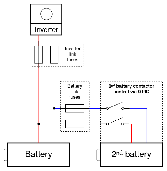
After the main battery is started, the system will automatically close the interconnect contactors for the second battery, if it's within 1.5V of the main battery. Note that if you skip the interconnect contactor and rely on only closing via CAN, you need to manually sync up the system first, otherwise you will blow the fuses.
Low voltage connection~
GPIO-controlled contactors~
If your batteries use GPIO-controlled contactors, you use these to attach the second battery to the DC link. Secondary battery does not use precharge (leave the precharge relay unconnected), and you can switch both positive and negative at the same time, from the same SSR. No need to add a secondary contactor:
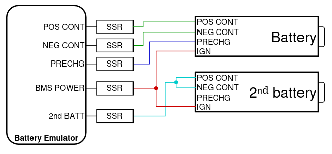
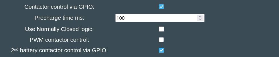
Enable 2ⁿᵈ battery contactor control via GPIO: in the Settings page. When the second battery voltage matches the main battery the extra contactor will engage and combine the two batteries into one large one.
Check out the pinout table for each board, to see which pin is defined to actuate the extra contactor.
TIP
If you enable PWM contactor control and you observe after a longer time that the second battery disconnects raising the event Too large voltage diff between the batteries. Second battery cannot join the DC-link, increase the PWM Hold value relatively to PWM Frequency Hz, to ensure the contactors remain held steadily.
CAN-controlled contactors~
To control the second battery if it only has CAN activated contactors, you need to an additional GPIO controlled contactor in series with it. External contactros controlled like this behave deterministically based on Battery-Emulator status. Contactors get connected directly to GPIO pins on the Battery-Emulator hardware, and the batteries are started up in a controlled manner. The second battery is allowed to join if the voltages are close enough.
When using batteries with CAN controlled contactors (Tesla/Kia/Hyundai etc.), since CAN control acts on its own by the BMS, it can be very hard to troubleshoot these systems, and figure out why a specific pack is not closing contactors properly, or why it is opening them. The behavior varies: either they have reliable contactor control (MG?), last-resort-opening (Kia?), or no real control (they just close and stay closed). There's the question of whether the battery is happy to close contactors with a live bus - some would see this as a welded contactor and potentially permanently lock out (Volvo?). The safest definitely is to have the extra contactor, unless it is known 100% that that type is happy without it (It seems MG Gen1 is happy without it).
If your setup has batteries with CAN-controlled contactors, it's enough to add a single-pole contactor to the 2ⁿᵈ battery contactor control via GPIO control, and intrerrupt only the positive or negative link. The internal contactors will still act on both + and - when it's time to do so.
Taking Double Battery into use.~
In the settings:

Example wiring diagram - Stark Box + 2x BMW i3 + Fronius Gen24~

CAUTION
Working with high voltage is dangerous. Always follow local laws and regulations regarding high voltage work. If you are unsure about the rules in your country, consult a licensed electrician for more information.