High Voltage wiring tips
DC wire sizing is a very important part of planning your battery build. Most inverters accept 6mm² or 10mm²(check your inverter manual for more info), but most EV packs are 50mm². This creates a small problem, you will need to step down this wire size. When stepping down, it's a good idea to install fuses directly near the battery, to protect your wiring.
Wires and fuses~
Wire gauge (cross sectional area)~
NOTE
Since multiple people have assumed 4-way connecting blocks to be 2x2, resulting in short circuit, please make sure to double check continuity for all components before installing!
- When selecting the hardware (wires, fuses, switches), make sure they are rated for the DC voltages in your system. Hardware designed for solar will often work great with EV batteries. Do note that if you are using a 600V battery, you need to buy hardware that is capable of 1000VDC, it is not enough to go with 500VDC certification.
-
Also keep in mind that longer DC cabling will cause larger voltage drops. Try to keep the DC wiring run as short as possible. 20-30meter is acceptable, but if you start to go longer distances (~80m?), you will need to have a much larger cross sectional area wire to avoid power losses. For instance 10-25mm² might be required when going longer. Use a voltage drop cabling calculator suited for your country to see the correct cable sizing you need for a specific distance. To get a picture of how much loss you can accumulate over various length of Cu and Al cabling, check out these calculators. Around 1% of loss can be acceptable. (ymmv, this is purely informational!)
-
DC cabling should also be installed in a conduit, to avoid any external factors damaging the insulation around the wires. The conduit material can either be plastic or aluminium, depends on what's typical in your region.
- 12V control/signal wire has the same limitations, increase cable cross sectional area to be able to go longer distances. Check out our tips for low voltage wiring page
- Avoid installing communication wires next to high voltage wiring, in order to avoid signal interference. Keep 300mm distance between AC/DC and CAN/Modbus cabling at all times when possible to avoid interference.
CAUTION
Verify polarity of HV system before wiring it to the inverter. Many EV batteries don't have markings which side is +/-, so doing a test run without the inverter connected is a good idea to ensure polarity. Incorrect polarity will destroy your system.
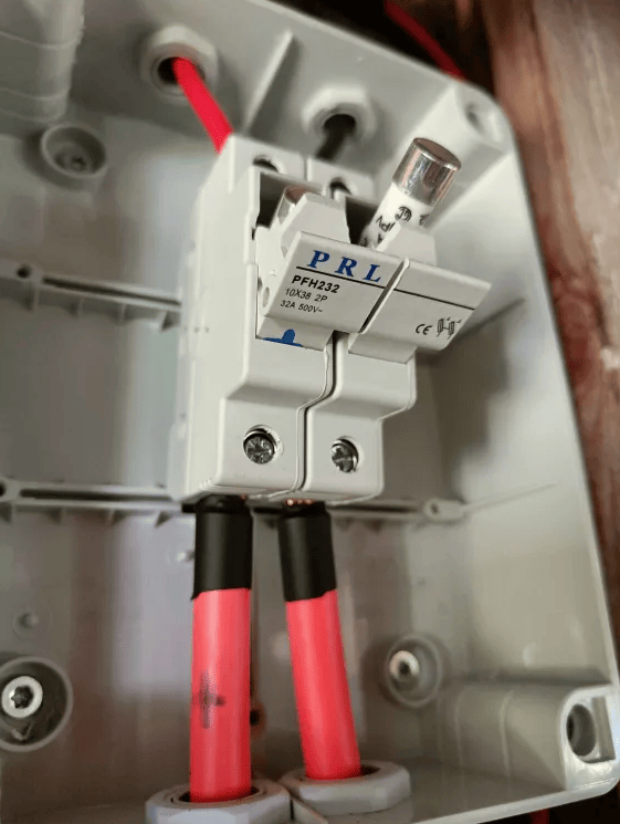
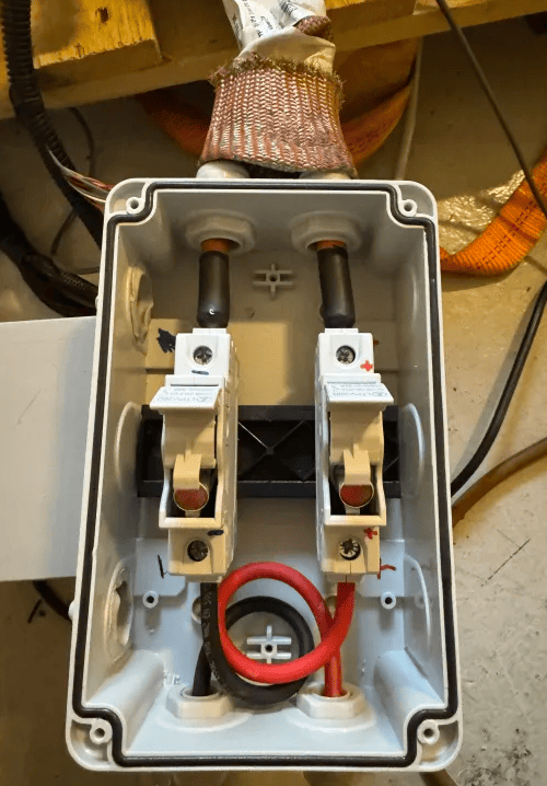
Example, 50mm² cable stepped down to 10mm², and at the same time fused off with a 25A solar DC ceramic fuse:
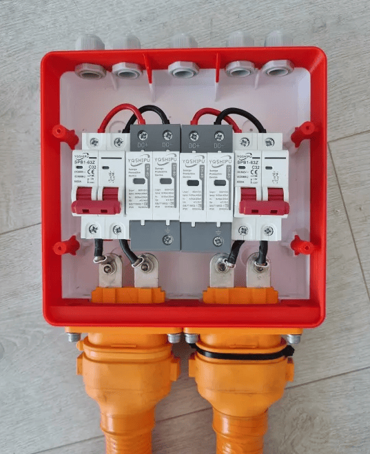
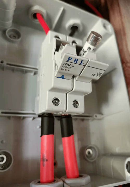
Example, two EV battery inputs stepped down to 10mm² using DC fuses:
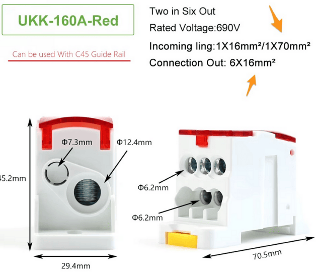
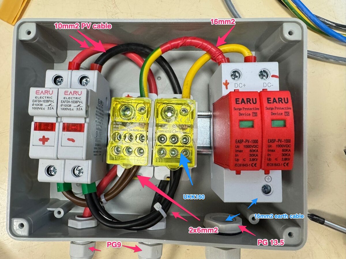
If you just want to step down the wire size (from 50mm² cable to 10mm² cable), you can use a terminal block such as UKK 160
DC Fuses~
How large fuse do I need?~
Sizing your fuse depends on your target power (kW) and your battery's voltage range — not its nominal voltage.
Inverters draw constant power, so as the battery discharges and its voltage falls, the current rises to compensate. The highest current always occurs at the lowest battery voltage. A fuse sized using nominal or full-charge voltage will be undersized, and may nuisance-blow during long discharges at low state of charge.
Always use the lowest voltage your battery will reach (minimum cell voltage × number of cells in series) for the calculation.
Example voltage range assessment
Zoe ZE40 is "96s" — 96 cells in series. Each lithium cell has a safe working window, typically 3.0V minimum to 4.2V maximum:
Pack minimum: 96 × 3.0V = 288V
Pack maximum: 96 × 4.2V = 403V
Example calculation, 5kW inverter with a Nissan LEAF battery (96s, 300–400VDC range rounded)
Current at full charge:  I = P/U = 5000W / 400V = 12.5A
Current at empty:        I = P/U = 5000W / 300V = 16.6A  ← sizing point
Fuse size = 16.6A × 125% ≈ 20A fuse required
The fuse must not be used as your current limiter. Set the inverter or Battery Emulator max discharge current below the fuse rating (≤80% is a good rule) so the fuse only acts on genuine faults. Fuses can either be DC Ceramic, or DC DIN-mounted fuses. Make sure the fuse you are purchasing is certified for DC and for the voltage range of your battery.
CAUTION
Polarized DC breakers should not be used. These are only intended for solar DC, with one direction of current flow. If these are used on batteries that have bi-directional current flow, they will break. For this reason, gBat fuses are recommended!
DF Electric 14x51 2-40A 600V DC fuses
DF Electric 22x58 40-80A 600V DC fuses
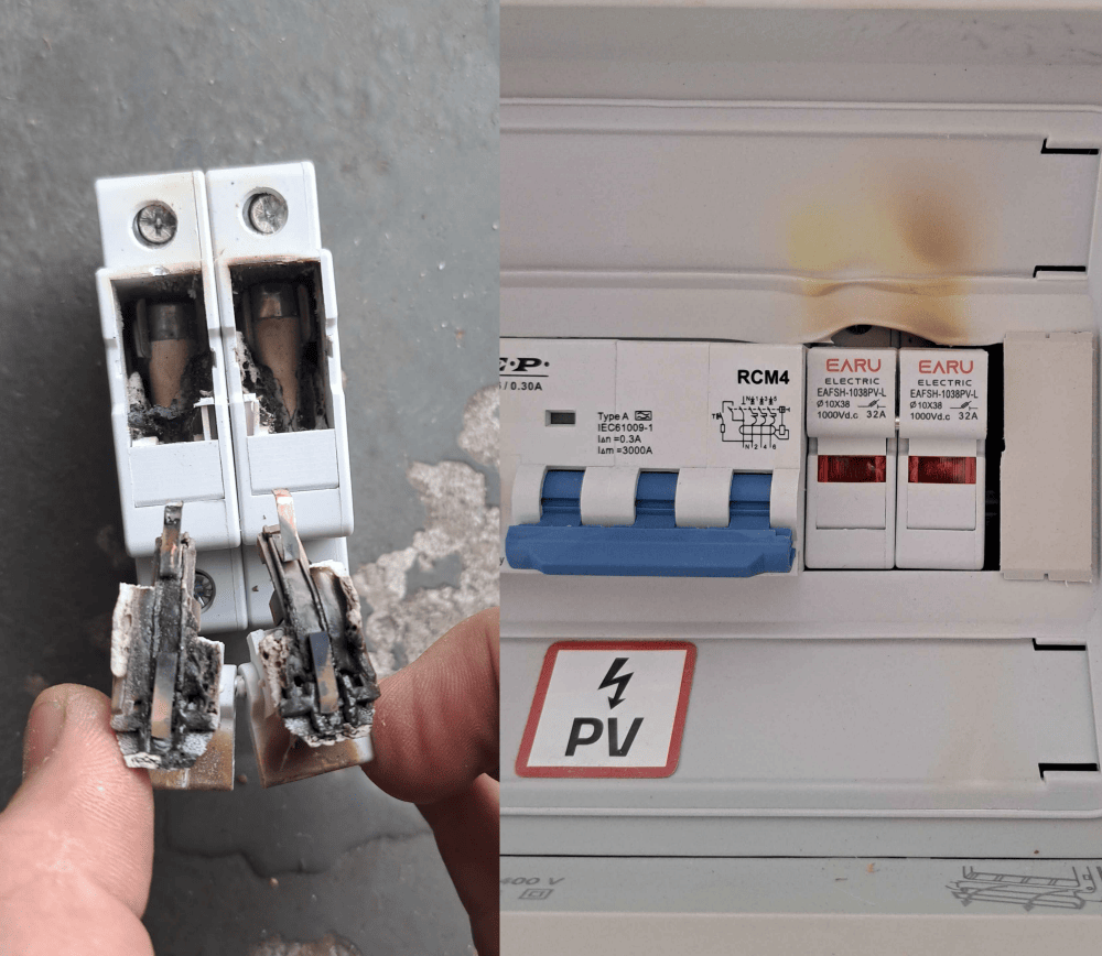
Don't buy cheap products from doubtable sources unless you intend to burn your house down (images courtesy of WJD on Dala's EV Discord):
Disconnect switches~
Some countries have legislation that dictate a need for DC disconnect switches (also known as DC isolation switch). The idea behind this is that these switches will be installed in a place where first responders and firefighters can easily turn off your solar/battery combination. Check your local legislation to see if this is required in your area.
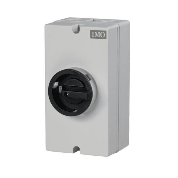
IP67 Waterproof 32A 1000V Disconnect Switch
Protective earth~
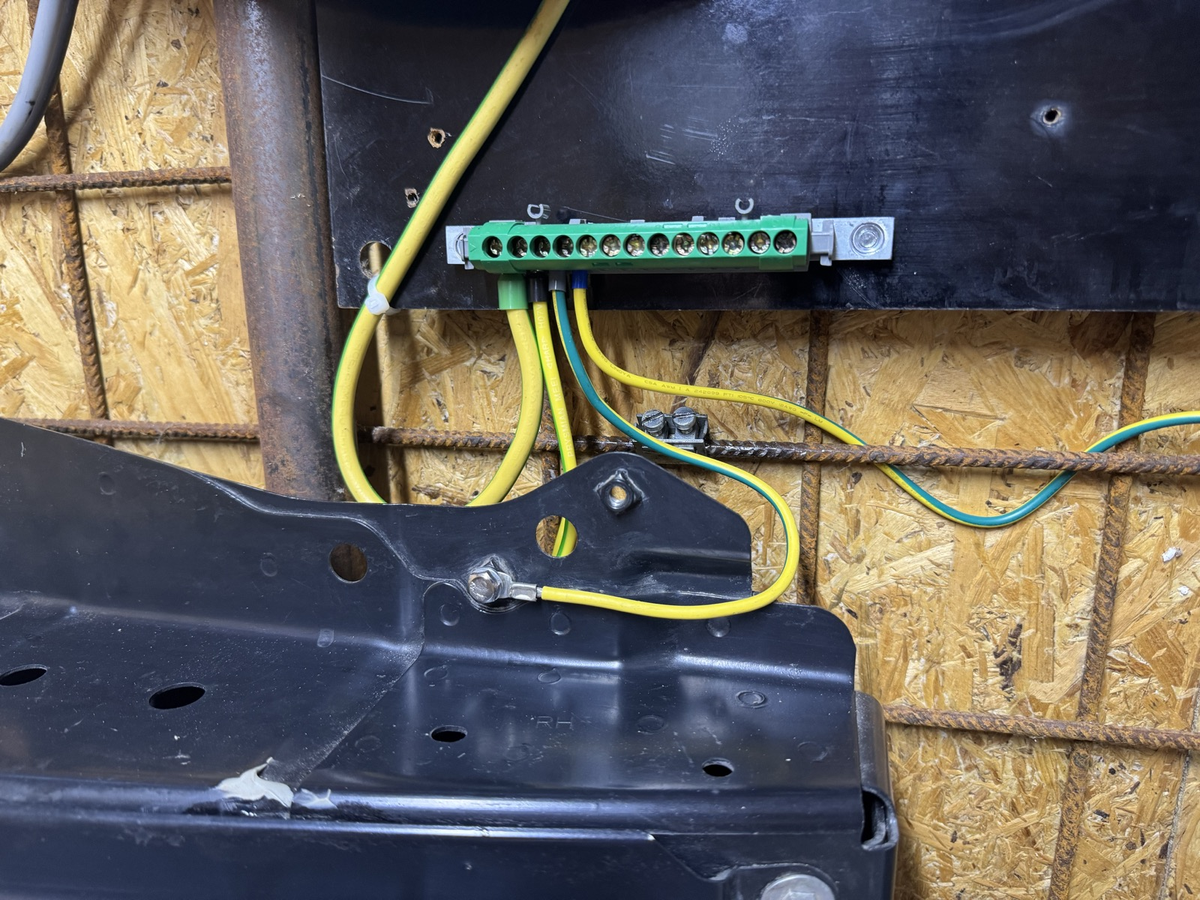
The battery case needs to be connected to protective earth (PE). This is required for a few technical and safety reasons;
- Signal integrity. Having the battery case sit at earth potential avoids any ground loops thru communication shield wires.
- CAN transceiver longevity. Failure to attach PE to battery case can damage CAN bus systems from ground loops thru shield wires
- Insulation testing. Your inverter will periodically test how safe the high voltage system is by measuring insulation resistance between HV+/- to PE. If the battery case is left freefloating and not connected to PE, any HV leaks might go unnoticed.
- If you are in a country that requires a residual current device in your electrical panel (GFCI/RCD), these also need to be able to accurately measure any DC leakage to PE and trip
CAUTION
Failure to connect battery case to protective earth can lead to dangerous situations where high voltage leaks are not detected
Check out the page with our tips for proper earthing.
Example, Nissan LEAF battery case and all other metallic parts connected to PE:
Loss of isolation  ~
~
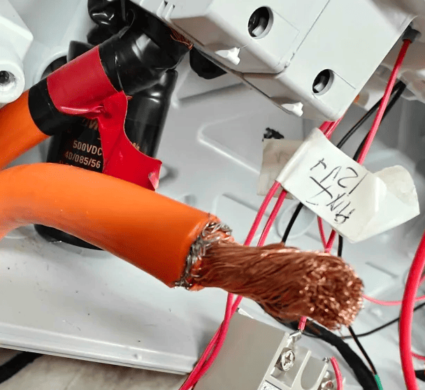
If either HV+ or HV- touches protective earth while the system is running, the solar inverter will detect this and throw an loss of isolation / insulation resistance too low error message, and stop operation. Troubleshooting this can be tricky, and requires extreme caution since high voltage can be present in protective earth.
Example, wire shielding cut too close to copper, making the shield touch HV-. This was causing inverter to stop operation
Start by checking the easy stuff, measure if HV wiring is leaking to PE. If the wiring is OK, the battery itself can also have an internal leak. These are much harder to diagnose compared to external wiring issues. Checkout this video for more example of leakage to ground youtube
Terminal tightness  ~
~
Electrical connections can loosen over time due to thermal cycling (expansion and contraction from heating and cooling during charge/discharge cycles). This is especially noticeable on high power DC systems. A loose connection increases electrical resistance, leading to localized heating, potential fire hazards, and voltage drops that reduce system efficiency.
- Why it's Important: Loose terminals are a leading cause of electrical failures. They can cause arcing, melting, and in severe cases, fires.
-
Materials Matter:
- Copper Lugs/Terminals: Check torque every 1-2 years.
- Aluminium Lugs/Terminals: Aluminium is more susceptible to "cold flow" or creep under pressure. Check torque annually.
-
Procedure:
- Safely de-energize the system and verify there is no voltage present with a known working multimeter
- Use a calibrated torque wrench and the correct socket.
- Consult your manufacturer's manual for the exact torque specification (e.g., 4-5 Nm or 35-45 in-lbs). On some terminals the torque value is stamped directly on them. Do not over-tighten, as this can strip threads or damage terminals.
- Visually inspect terminals for signs of corrosion, melting, or discoloration.
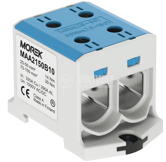
Example of terminal with torque values printed on it.
Coolant (for Liquid-Cooled Systems)  ~
~
Liquid cooling is used in some EV batteries to manage battery temperature. Maintaining the coolant is vital for thermal management and preventing corrosion.
- Why it's Important: Low coolant levels can lead to poor heat dissipation, causing the battery to overheat and degrade rapidly. Old coolant loses its anti-corrosive properties, leading to leaks and cooling system blockages.
-
Coolant Level Check:
- Frequency: Check every 3-6 months.
- Procedure: With the system off and cool, inspect the coolant reservoir. The level should be between the "MIN" and "MAX" marks. Top up only with the manufacturer-recommended coolant type. Never mix different coolants.
-
Coolant Replacement:
- Frequency: Typically every 3 to 7 years, but follow the manufacturer's strict interval.
- Procedure: This is often a very installation specific task. It involves draining the old coolant, flushing the system, and refilling with new, premixed coolant while ensuring all air is bled from the lines to prevent airlocks.
See also~
Examples of wiring installs~
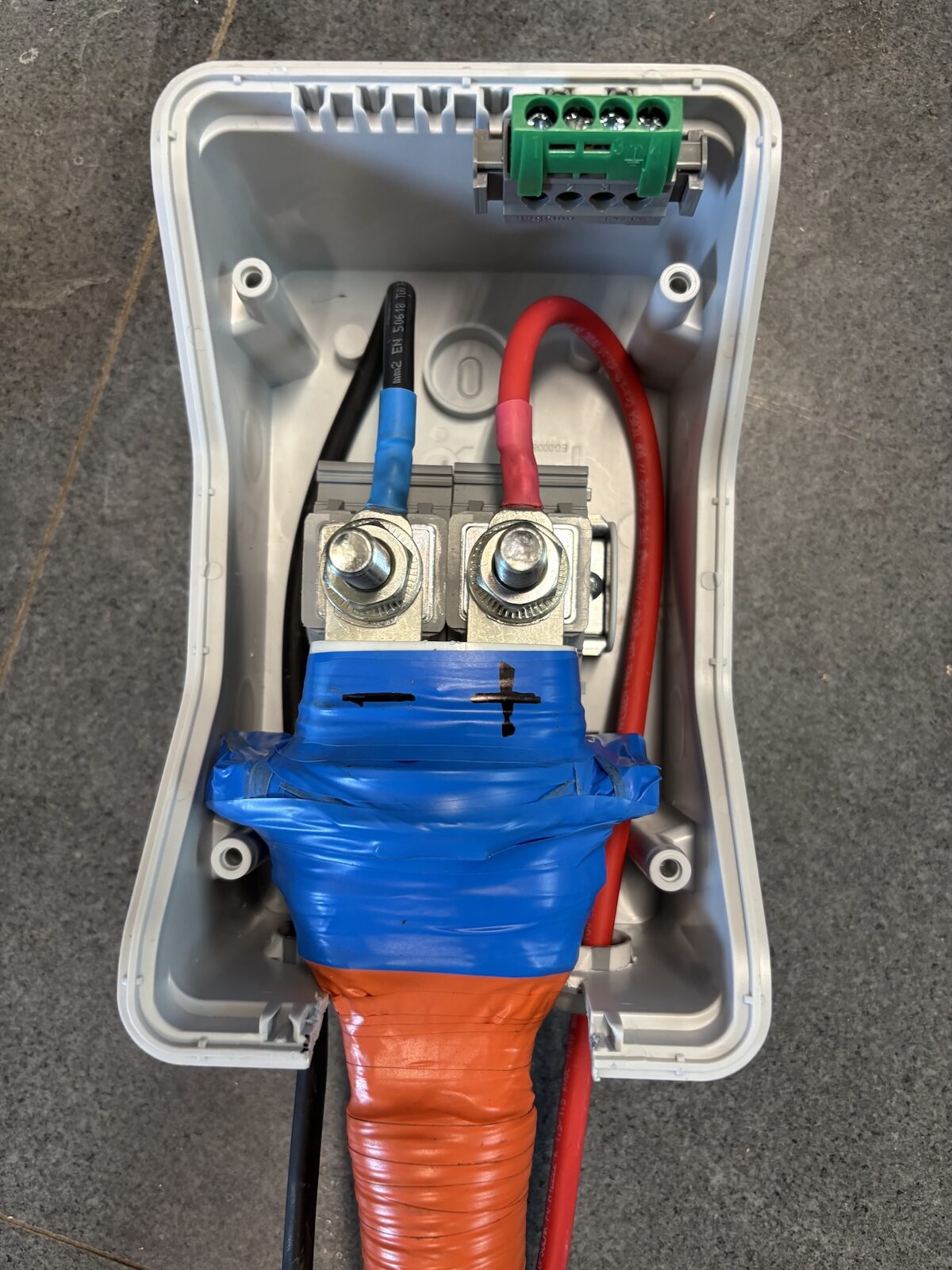
Here are some examples on how to wire up the high voltage output from the battery, into a fusebox or DC junction box.
Nissan LEAF~
Phoenix 3049408 DIN rail connectors to use with unmodified cable:
BMW I3~
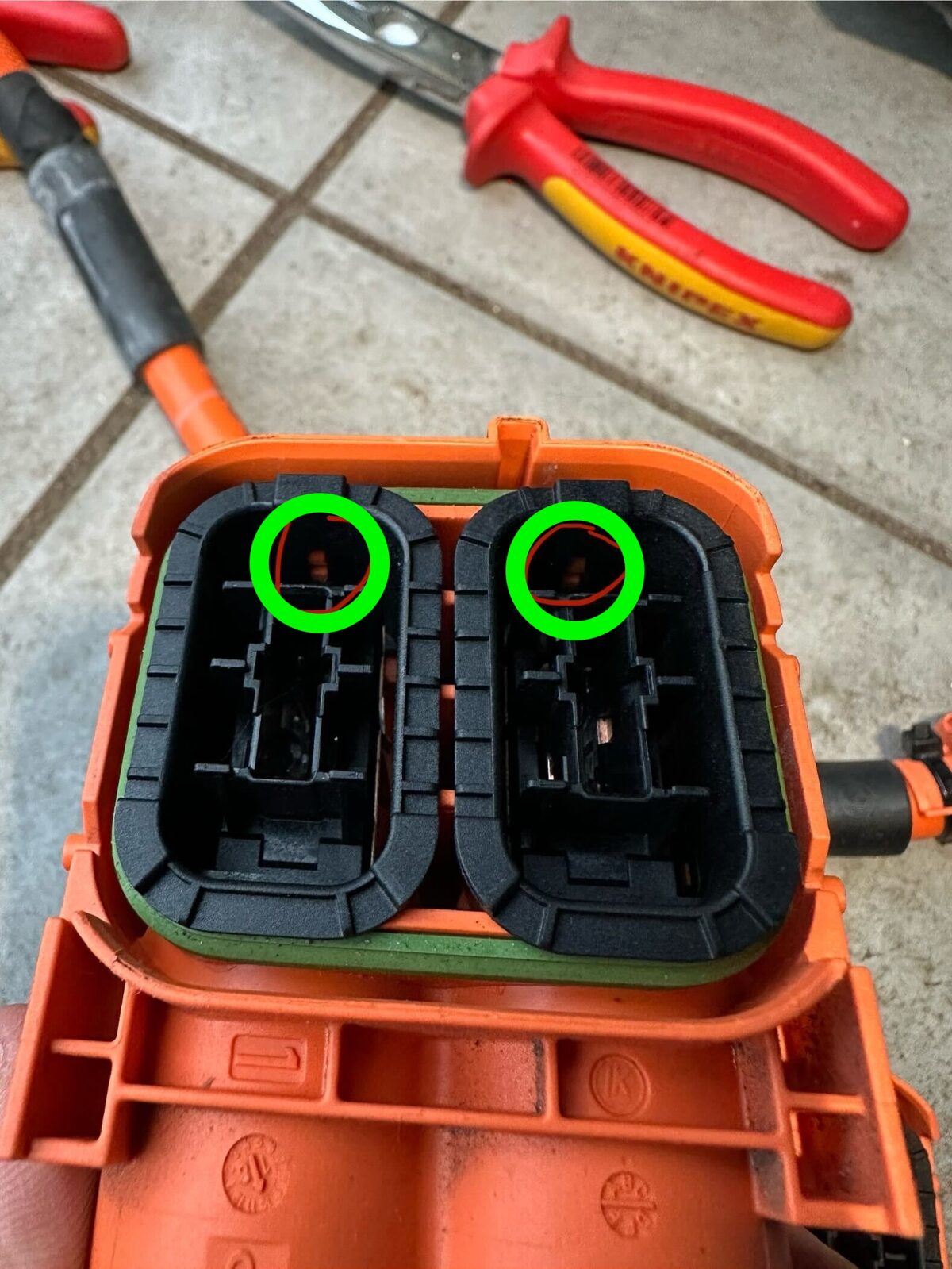
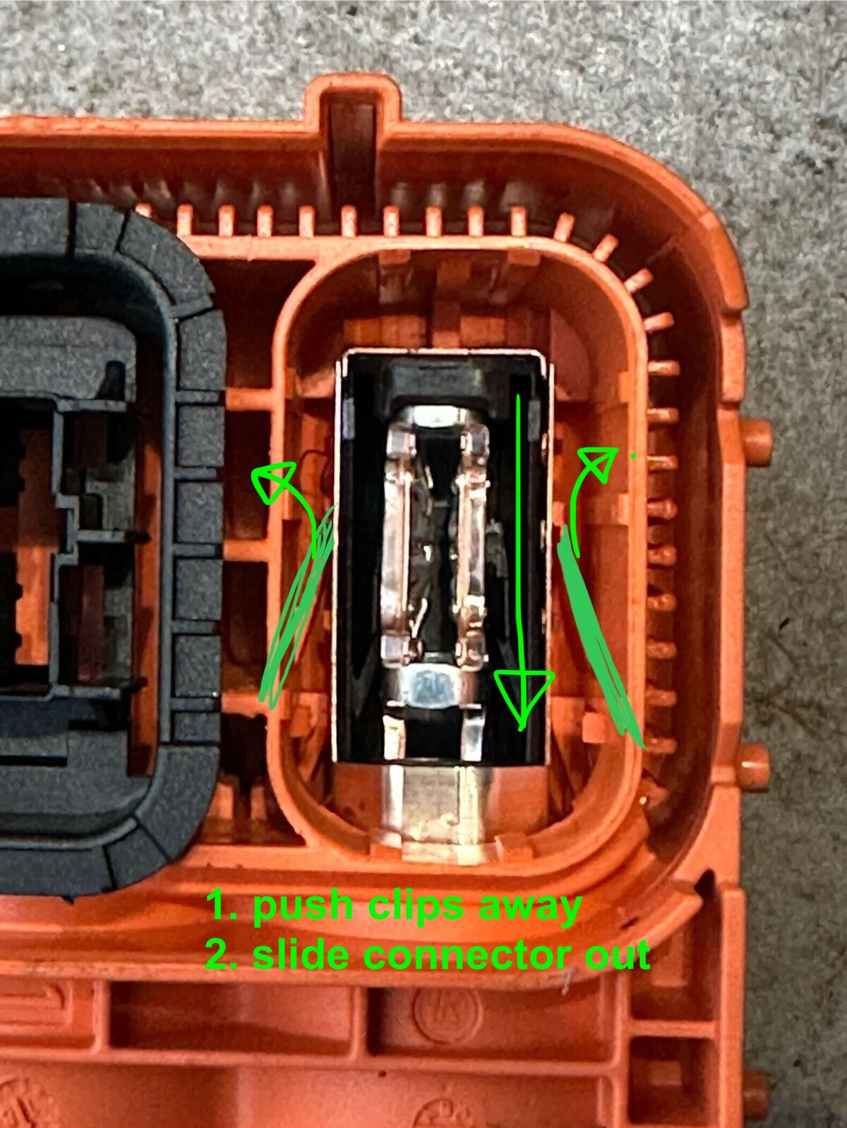
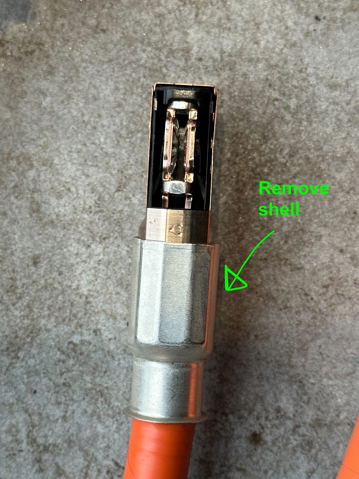
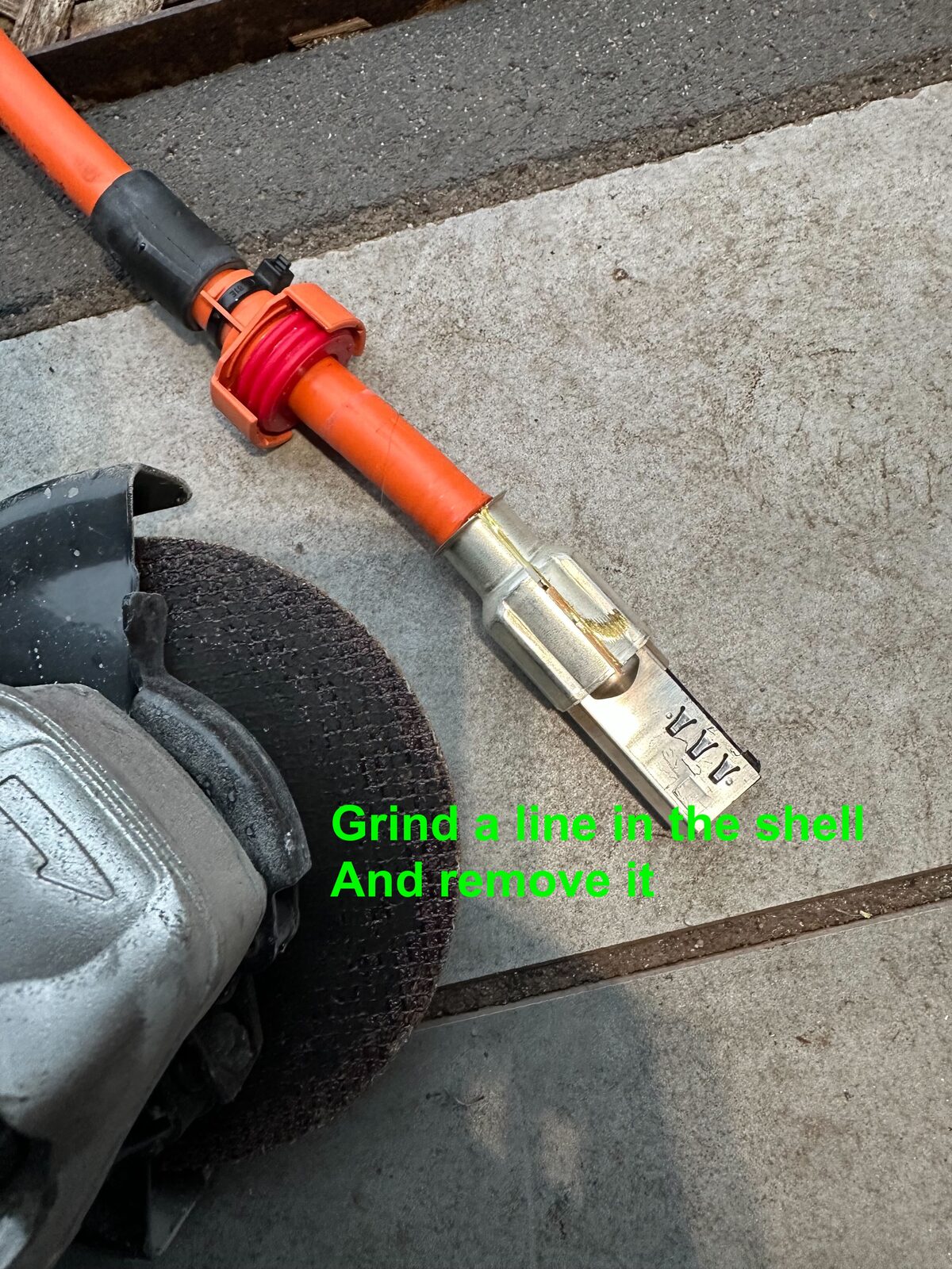
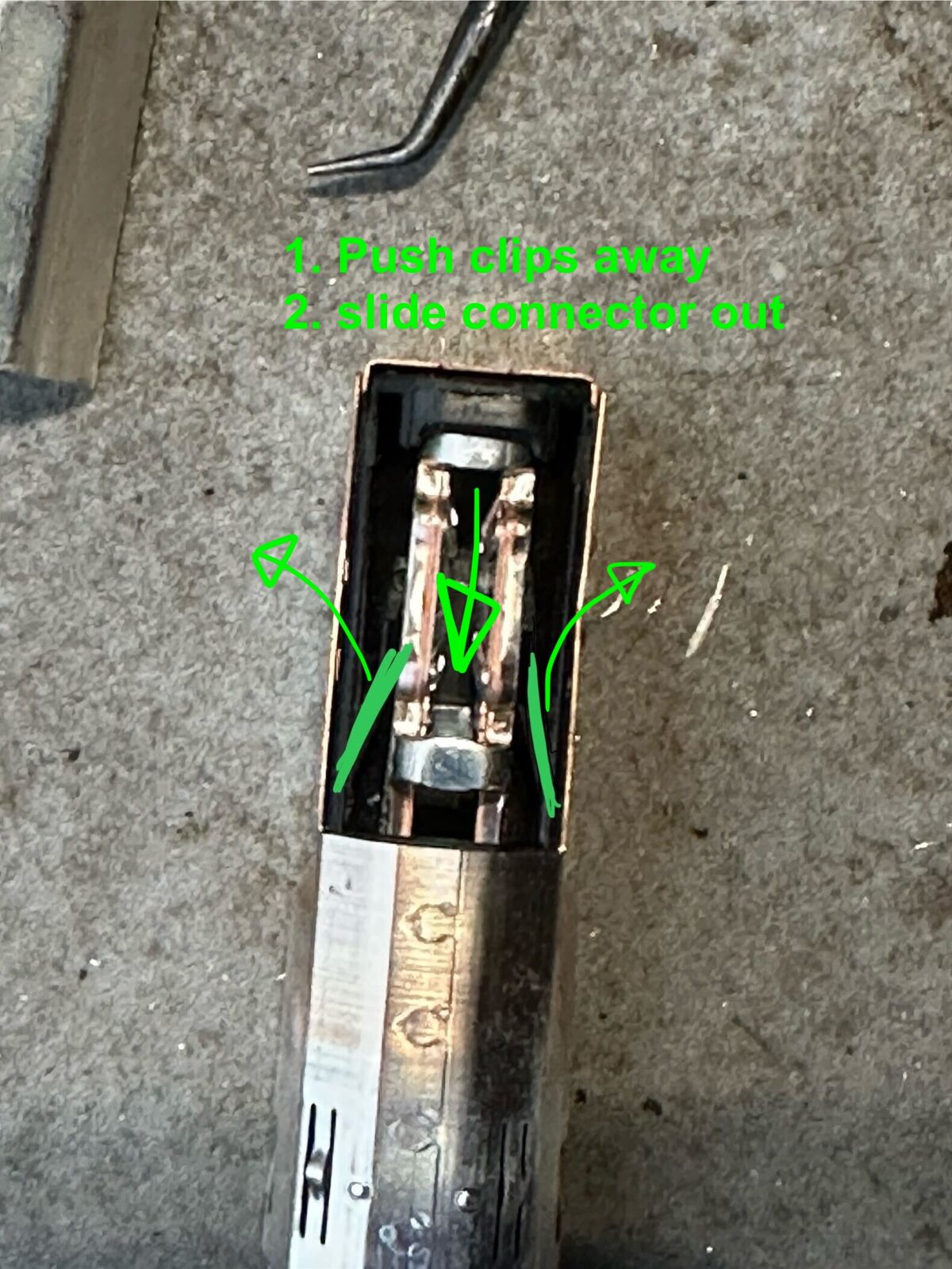
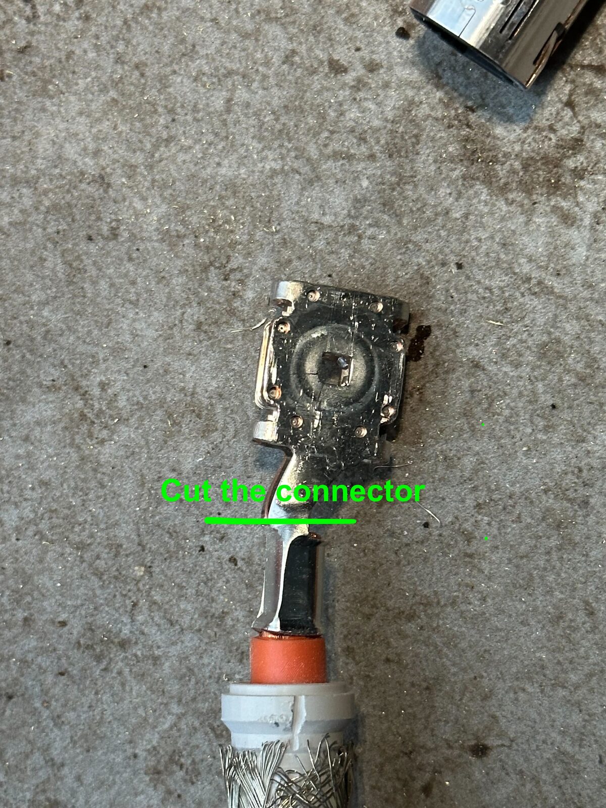
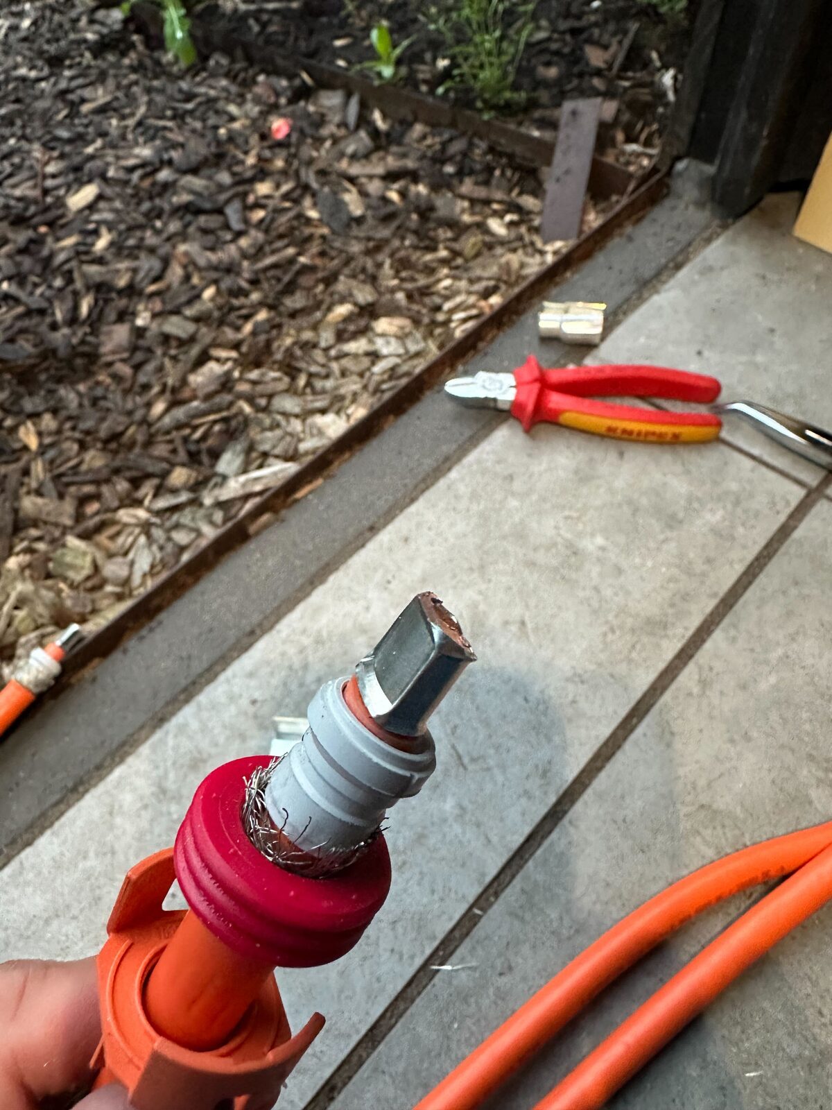
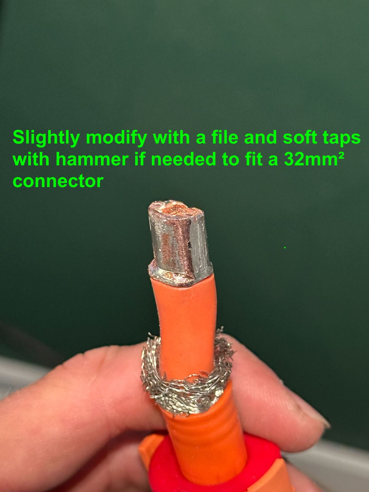
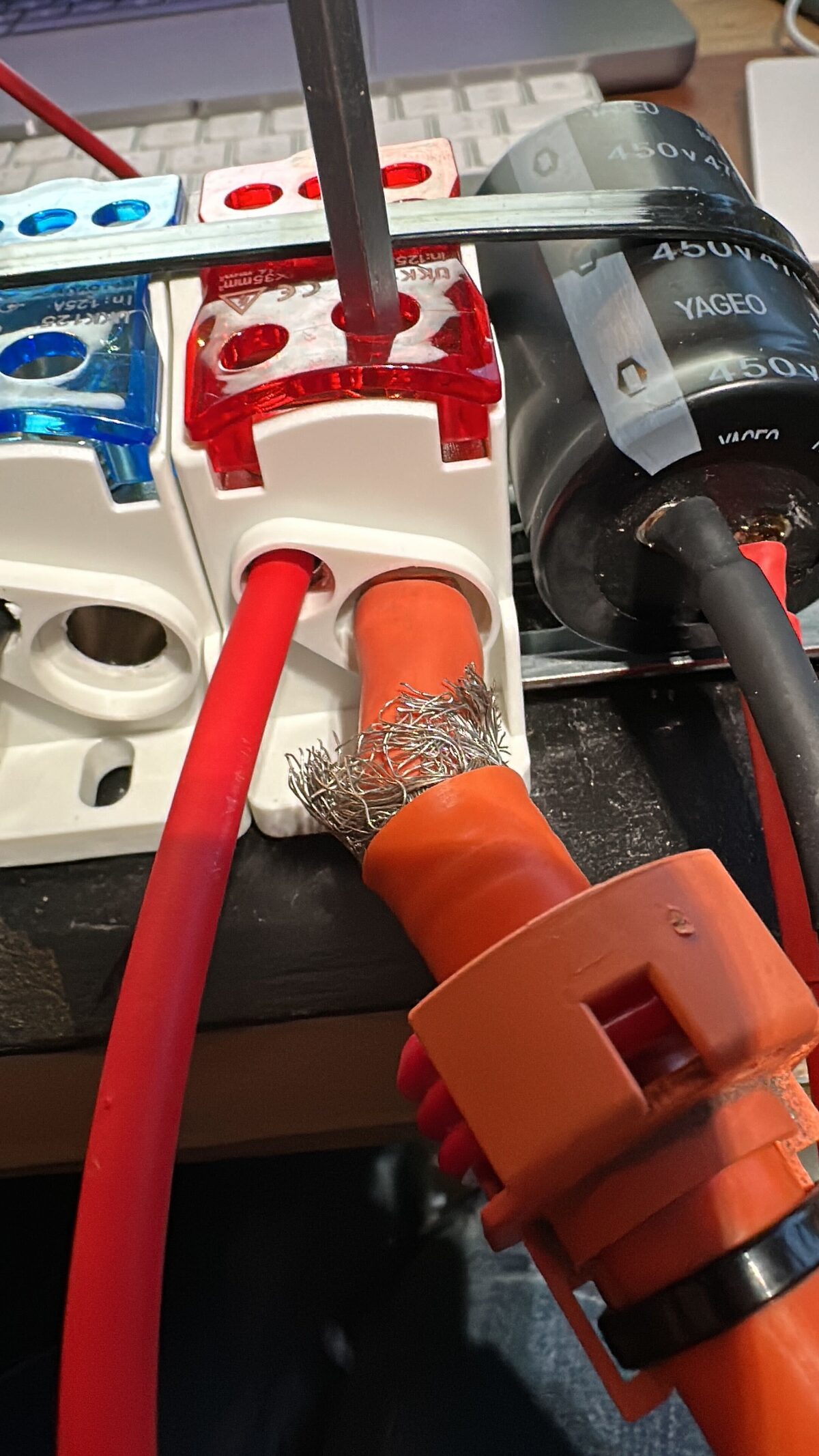
The bmw I3 uses a 35mm² high voltage cable. To connect it to a terminal block and go down in size to a more manageable 10mm² you would need ferrules for these stranded wires to not damage them. This can be done by cutting off the old connector and using a ferrule and crimping them. These tools are not so common for consumers. An alternative for this is modifying the connector and use the current connector as ferrule so you don't have to buy or rent tools to achieve a non-stranded wire for the thermal block with size 35mm². Use at your own risk!
CAUTION
Working with high voltage is dangerous. Always follow local laws and regulations regarding high voltage work. If you are unsure about the rules in your country, consult a licensed electrician for more information.