BECom
MCU / flash: ESP32-S3 (Xtensa LX7 dual-core, 240 MHz), 16 MB flash.
The BECom (Battery Emulator Companion) hardware is an open source hardware design created specifically for the Battery-Emulator project. It aims to replace the devkit-plus-adapters approach with a single purpose-built board: everything a typical stationary storage install needs — two battery CAN FD buses, contactor drivers, isolated inverter comms, a 12 V native power supply and an optional battery backup — is already on the board and wired to pluggable screw terminals.
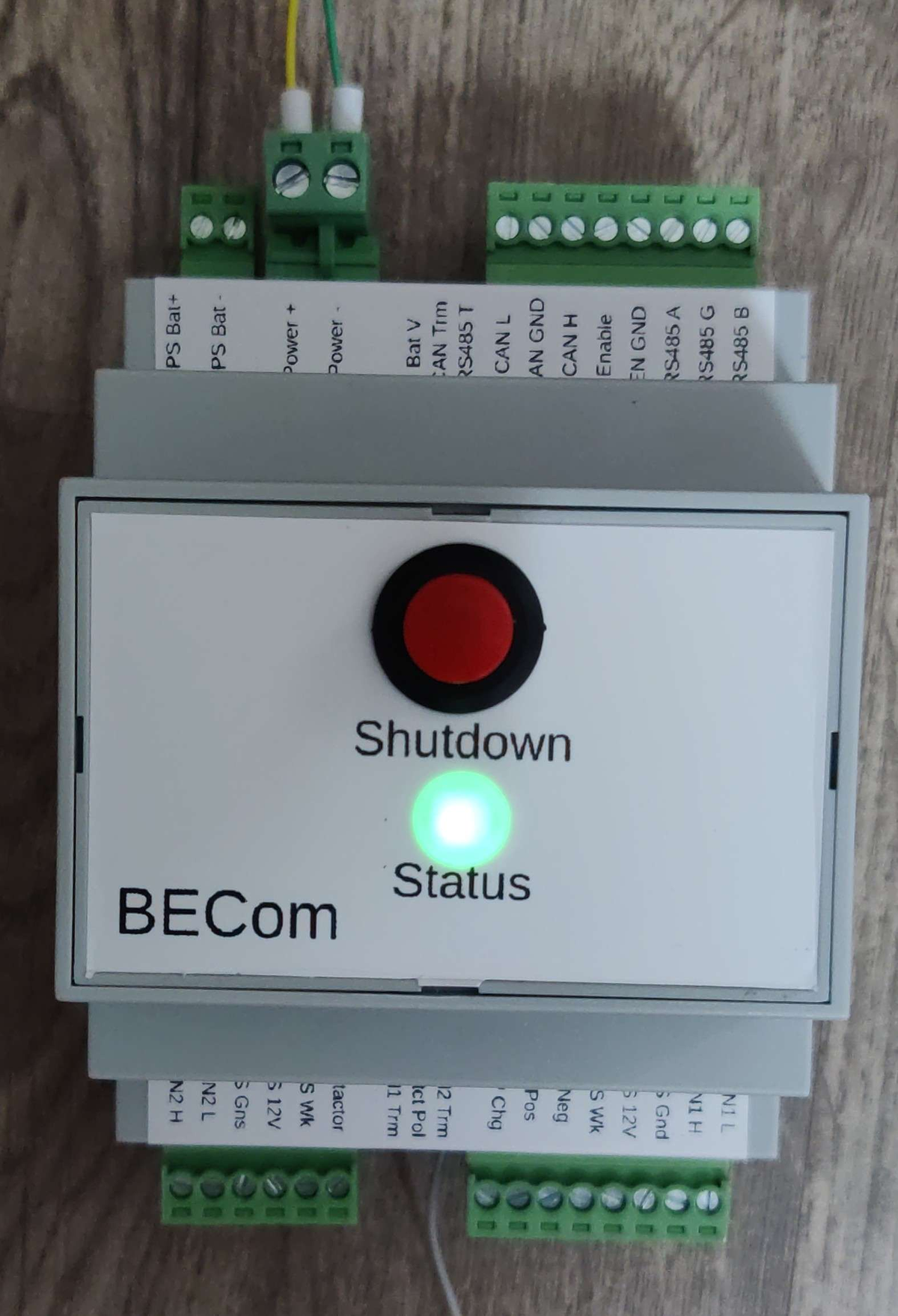
The board is built around an ESP32-S3-WROOM-1U module (16 MB flash, external antenna) on a 4-layer, roughly 64 × 86 mm PCB that is designed to fit a Kradex Z-108 enclosure. It is powered directly from the 12 V system rail rather than from USB: the input accepts a wide range with a 20 V TVS, reverse-polarity and backflow protection, and an undervoltage lockout that starts the board at about 9.0 V and shuts it down at about 7.75 V.
A built-in UPS stage takes a separate backup battery on its own terminal, charges it (13.7 V for lead-acid/LiFePO4 or 12.3 V for lithium, ~543 mA), and switches over automatically when the main input drops below about 9 V, so the emulator keeps running and can shut the batteries down cleanly on a power loss. Each battery's BMS 12 V supply is fed through its own 5 A electronic fuse with undervoltage lockout at 8.24 V and overvoltage protection at 19.73 V, so a short on a battery harness cannot take down the board.
Contactor outputs are driven by high-side/low-side MOSFET pairs, and a DIP switch selects the drive polarity — the same output can switch either the positive or the negative side of the contactor coil, so the board suits both wiring conventions without modification.
USB-C is provided for flashing and serial logging, next to Boot and Reset buttons. A 2×15 (1.27 mm) expansion header brings out spare GPIOs, I²C and the RGB LED signal for an expansion board or front panel.
Interfaces~
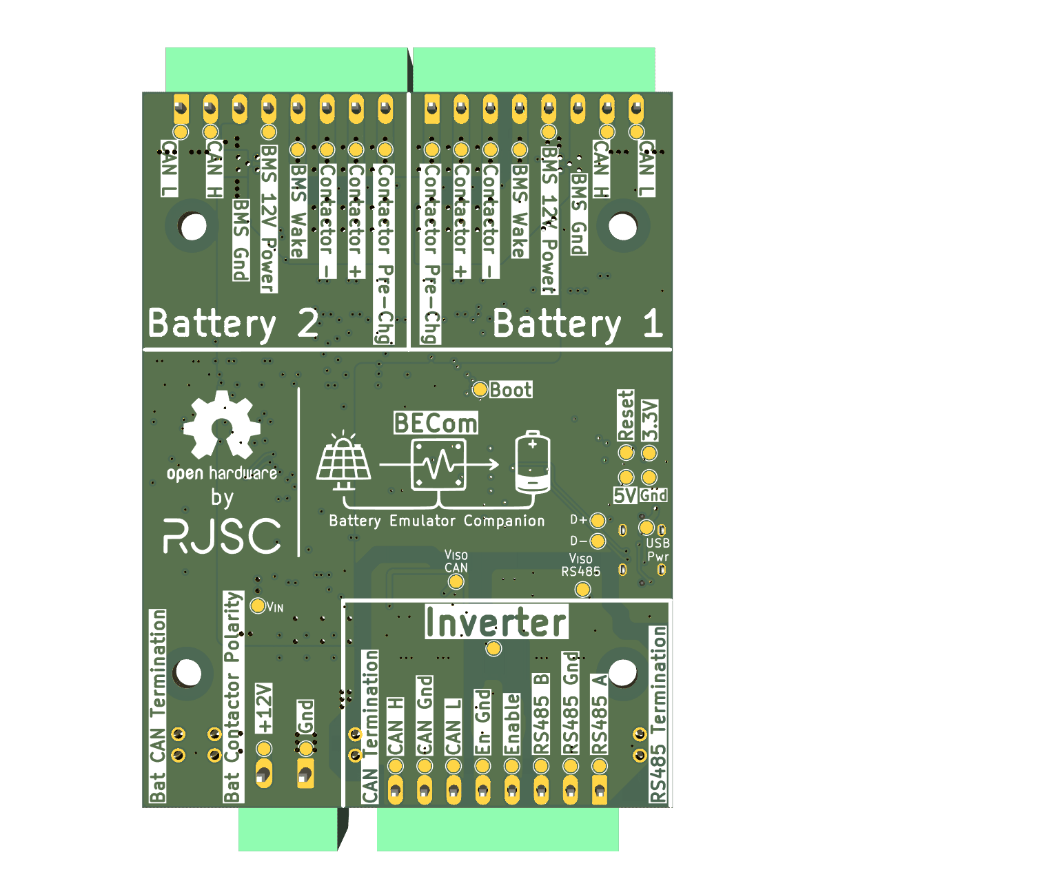
The board has IO for 2x CAN batteries, along with contactor control for each battery. It also features a CAN interface for the inverter, and a Modbus RS485 connector. The inverter comms (CAN and RS485) are electrically isolated.
Both battery buses are CAN FD, each handled by its own MCP2518FD controller sharing one SPI bus. Battery 1 gets three contactor outputs (positive, negative and pre-charge), battery 2 gets one. Every battery connector also carries the switched 12 V BMS supply, ground and a BMS wake line.
| GPIO | Function |
|---|---|
| 0 | BOOT button — long-press options available |
| 1 | BMS Power output — inverted logic, HIGH shuts the battery down; held across a reset/OTA reboot |
| 2 | Battery wake-up 1 (WUP1) |
| 3 | SMA inverter contactor enable input |
| 5 | Status LED (addressable) |
| 8 | Native CAN TX (inverter CAN) |
| 9 | Second MCP2518FD (CAN FD battery 2): INT |
| 10 | First MCP2518FD (CAN FD battery 1): INT |
| 11 | First MCP2518FD: SDI |
| 12 | First MCP2518FD: SCK (bus shared with the second MCP2518FD) |
| 13 | First MCP2518FD: SDO |
| 14 | First MCP2518FD: CS |
| 15 | RS485 TX |
| 16 | RS485 direction control (DE/ /RE for half duplex) |
| 17 | RS485 RX |
| 18 | Native CAN RX |
| 21 | Second MCP2518FD (CAN FD battery 2): CS |
| 37 | Second battery contactors output (battery 2 negative contactor) |
| 41 | Battery wake-up 2 (WUP2) |
| 45 | Precharge contactor output (battery 1 precharge) — or HIA4V1 precharge control |
| 46 | Equipment stop input — tied permanently low in hardware v1 |
| 47 | Positive contactor output (battery 1 positive) — or inverter disconnect contactor output |
| 48 | Negative contactor output |
The inverter side is fully isolated: an isolated CAN transceiver, an isolated RS485 transceiver and an optocoupled Enable output (for inverters such as SMA that expect a dry contact). Each isolated domain has its own supply, common-mode chokes, gas discharge tubes, TVS diodes and resettable PTC fuses on every line.
Bus termination is set with DIP switches on the board, marked CAN Term, RS485 Term, CANFD1 Term and CANFD2 Term. The same switch blocks also carry Contactor Polarity and UPS Bat V, which selects the UPS Battery Charge Termination Voltage between 12.3V for 3S Li-Ion packs and 14.7V for Lead-Acid and 4S LFP packs. A small 2×2 header lets the two CAN FD buses be bridged together when both batteries share one bus.
Hardware info~
The hardware has more details on the project GitHub repo
The KiCad project, schematic PDF and footprint libraries are published there under GPL-3.0.
Purchase link~
BECom is not currently sold as a finished product. The design files are open source, so boards can be ordered and assembled from the KiCad project in the repository above.
NOTE
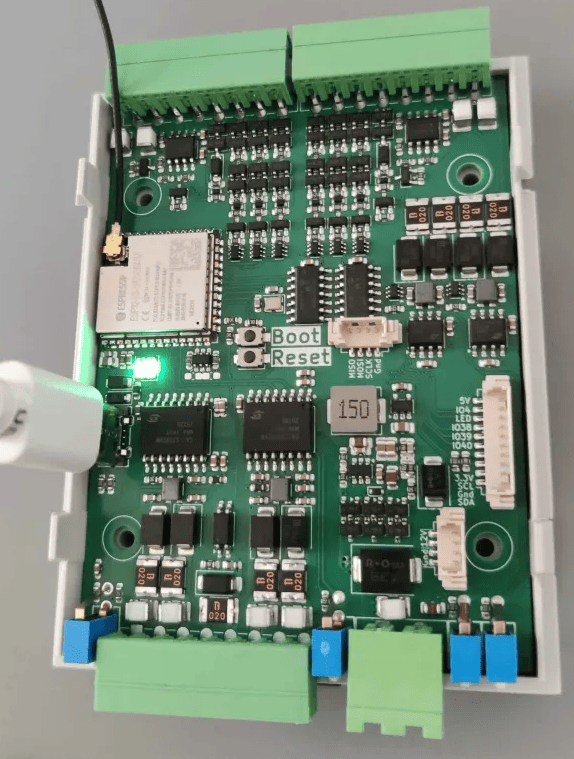
This has an included Antenna that needs to be mounted for good Wifi performance. Failure to install this will lead to connectivity issues.
Installing the software~
Follow the quickstart guide to install the Battery-Emulator software onto the board for the initial setup.
Over the air (OTA) software updates~
When updating this board OTA, be sure to select the software marked for this board.
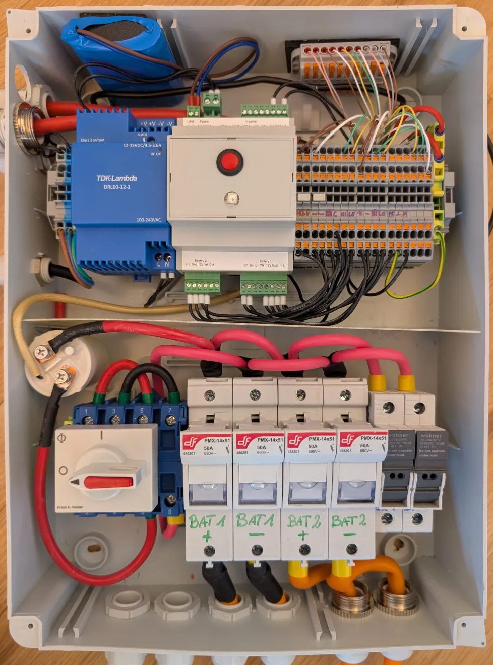
Example build~
See also~
- BOOT button for special features to enable AP, wipe wifi settings or factory reset the device
- CAN add-on MCP2518FD for an additional CAN interface
CAUTION
Working with high voltage is dangerous. Always follow local laws and regulations regarding high voltage work. If you are unsure about the rules in your country, consult a licensed electrician for more information.