Fronius
Types of compatible Fronius inverters~
The code works with the following Fronius inverters:
- Fronius Primo Gen24 Plus (all sizes) ✅
- Fronius Symo Gen24 Plus (all sizes) ✅
- Fronius Symo Gen24 Plus SC 12.0 ✅
- Fronius Symo Hybrid 3.0/4.0/5.0-3-S ✅ (ℹ️ Legacy, no longer available)
- Fronius Verto Plus (all sizes) ✅
On the date of 23.04.2025 Fronius deployed a firmware update that momentarily broke compatibility with Battery-Emulator. This was fixed and interoperability was restored.
- ROW 1.35.8-1 (Working ✅ ) worked with BE versions below 8.11.0
- ROW 1.36.5-1 (Breaks ❌ ) worked with BE versions above 8.12.0
- ROW 1.41.11-1 works with the current BE version (as of 2026-08-12).
It is recommended to always use latest software version of both the Fronius inverter and the Battery-Emulator.
Advice
Always read manufacturer's release notes before upgrading the firmware. You can save yourself from a serious amount of trouble by not upgrading to a version which may state that radically changes compatibility level with the emulated battery. Downgrading Fronius firmware to old versions is not possible.
Hardware limits  ~
~
- Fronius GEN24 Symo 3-5kW inverters are capped to max 12.5A on the battery port.
- Fronius GEN24 Symo 6-12kW inverters are capped to max 22A on the battery port (also the SC model).
- All Fronius GEN24 Primo inverters are capped to max 22A on the battery port.
- All Fronius Verto inverters are capped to max 50A on the battery port.
This means that if you have a high voltage battery (450V), you will see much higher charge/discharge power (22A x 450V = 10kW), compared to a low voltage battery (22A x 250V = 5,5kW)
Keep this amperage limit in mind when choosing a battery for the Fronius!
Software limits 
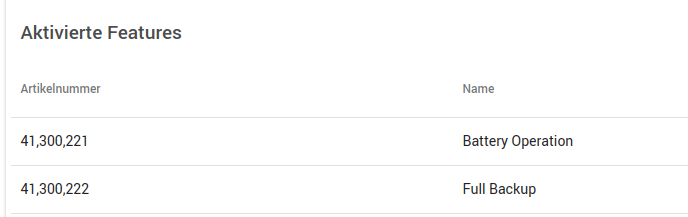
There is a non-Plus variant of Gen24 available, for this you have to purchase a battery license before you can add a battery to the configuration. In System > Information > License you should see something like below. Contact your installer incase "Battery Operation" feature is missing!
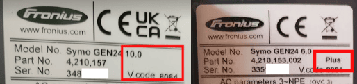
This can also be seen from the label on the inverter, incase "Plus" is missing:
Setting up the Fronius inverter with Battery Emulator~
You will need a technician login to the inverter to make changes to the setup. Contact your solar installer in case you don't have the technician login!
NOTE
You will also need a Fronius Smartmeter so that the system can measure consumption and generation.
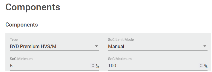
Setup for battery operation is done via the Solar.start app or Device Configuration > Components > Add Component > Battery. Select BYD HVS/M (2020-25):
After adding the battery, connect the Modbus/RS485 terminals of the Battery-Emulator hardware to the inverter (Waveshare ESP32‐S3‐RS485‐CAN and LEAF battery example):
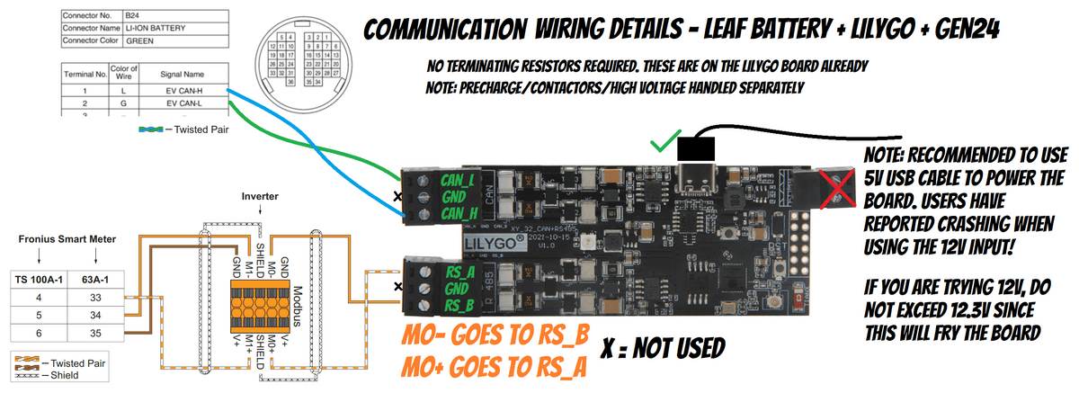
When the low voltage communication is handled, also connect the high voltage side (Nissan LEAF battery example):
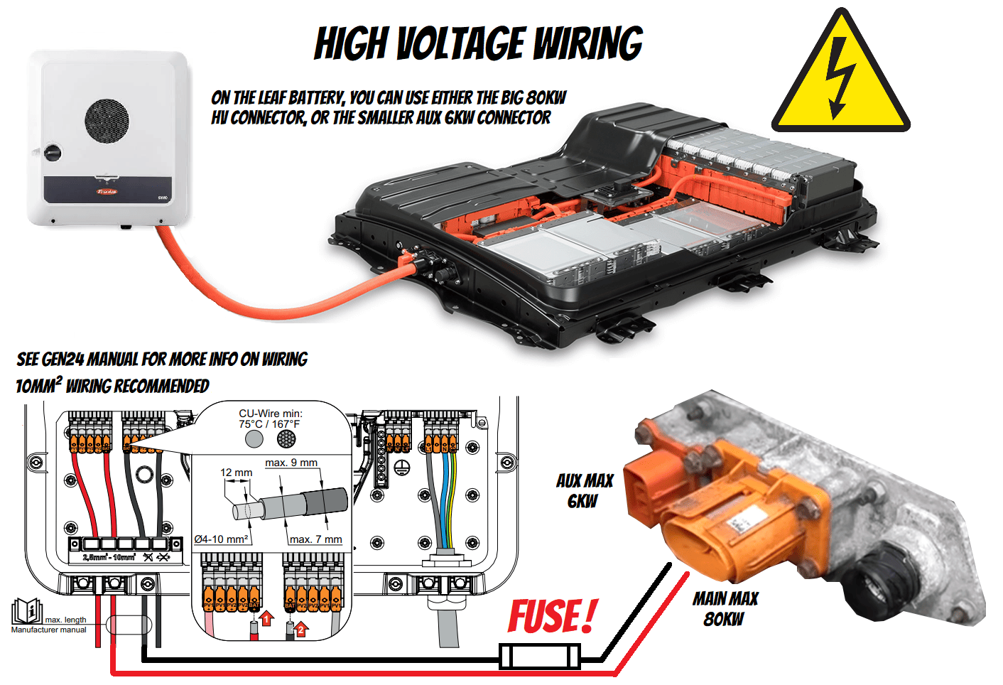
WARNING
New hardware requirement for Fronius  Battery voltage is reported towards Fronius inverters only after contactors are engaged. This means that old legacy installs using manual A/B/C switches for turning on battery contactors will no longer function with Fronius inverters. Only automatically controlled contactors via GPIO or CAN will work. This is a new stricter safety requirement to get the Fronius inverter to startup faster and with less errors.
Which protocol to use~
For this inverter type, use the option called BYD 11kWh HVM battery over Modbus under the Inverter Protocol setting. Also select the Inverter interface as Modbus.

NOTE
If you intend to use the Periodic Reset option with your battery, make sure to enable the "Defer reset if SOC less than 15%" option to avoid charging from grid if you reached the reserved level, and if Battery Emulator would want to do that at night.
Notes on Scaled SOC + Fronius min/max SOC~
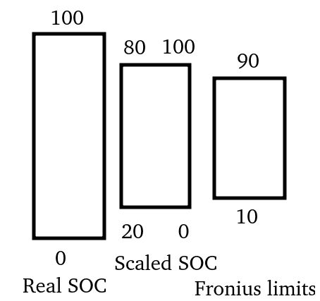
In the Fronius settings it is possible to configure "SoC Minimum" and "SoC Maximum" values. If you are using the Rescale SOC functionality in the Battery-Emulator, you will be applying double-rescaling of the usable capacity. It is recommended to always leave in Fronius the "SoC Maximum" to 100%, and adjust the "SOC max percentage" setting in Battery Emulator instead, to be able to take advantage of the "Charge power tapering based on SOC" which avoids power oscillations.
Avoid double-rescaling:
IMPORTANT
Fronius's BYD HVS/M (2020-25) implementation limits SOC minimum to 5% to avoid battery undercharge when sitting idle empty. It does a trickle charge/discharge cycle during an Energy saving mode procedure. Thus, if you enable Rescale SOC in Battery Emulator, keep in mind of this requirement at the low end.
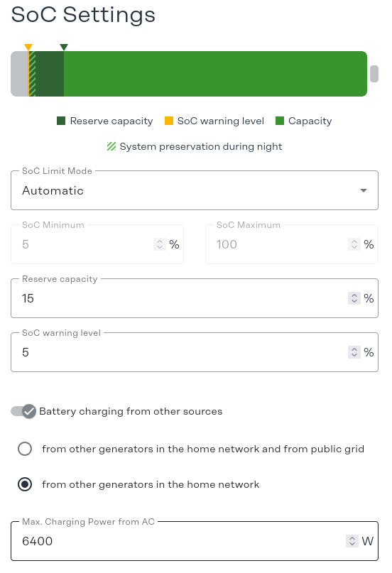
Optional setting: If you have multiple AC coupled inverters in your network, and they all reside behind the SmartMeter, you can enable Battery charging from other sources and select from other generators in the home network.
Starting and stopping the system~
When turning the system on, follow this startup procedure. Work quick, to avoid the inverter getting stuck in battery not detected mode, but pay attention to each step.
Startup~
- Power on the Battery-Emulator hardware and the EV battery respectively
- Turn on the Solar DC switch and the Battery DC switch if there is any
- Set the DC disconnector to the "On" switch position on the Fronius inverter
- Start the Fronius inverter via AC breaker
- Wait until contactors close at the EV battery (CAN controlled / GPIO control), and Fronius will start to use it
Shutdown~
Important to note when shutting down is to not open any DC breakers/isolators under load! Doing so can cause DC arcs and prematurely wear them out, and in worst case start a fire.
-
Signal to the inverter that battery is not available, with any of the following options:
-
Press PAUSE in the Webserver (best option)
-
Press optional Equipment stop if installed
-
Press Open contactors in the Webserver
-
-
Once Fronius stops using battery after a few seconds (verify in app to make sure) it can be powered down
- Turn off the Fronius inverter via AC breaker
- Turn off the Fronius inverter via the DC switch on the Fronius itself
- Turn off the Battery DC isolator switch
- Turn off the Solar DC isolator switch
Day to day monitoring~
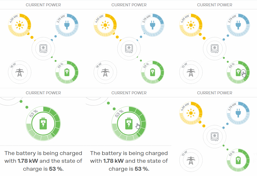
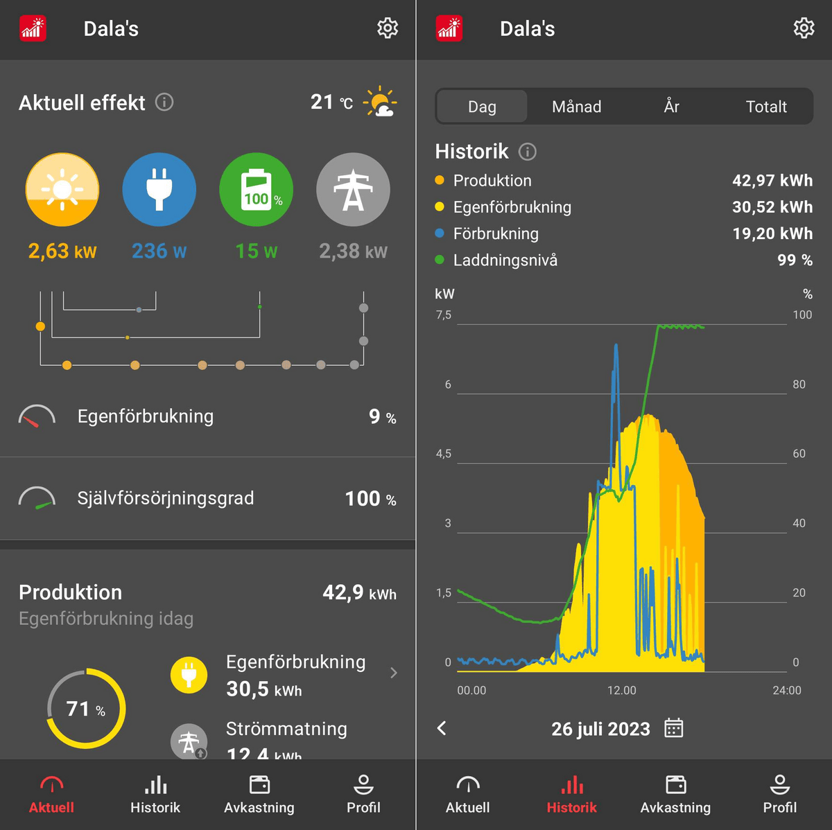
The performance of the system can be tracked with the app "Solar.web". This app gives direct info on current output/input, SOC% level of battery, graphs, and more. No settings can be changed via this app, but it is a great tool for visualizations and quick status checks. You can also see at a glance if an inverter firmware update becomes available for you.
Troubleshooting~
Battery not detected~
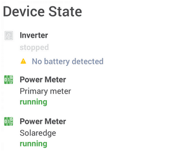
If you see No battery detected or No battery voltage measured but battery is active in the Service Messages:

Then verify the following:
- Make sure High Voltage is present on inverter battery input. Also make sure the DC isolator switch on the front of the Fronius is turned ON
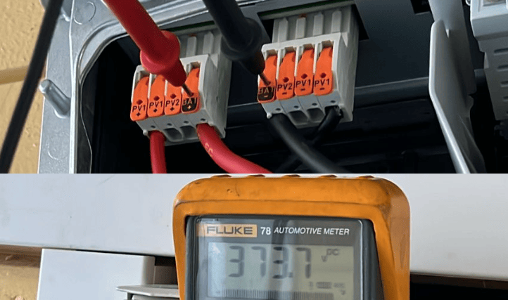
- Make sure the Precharge/Positive has not been accidentally swapped (Easy mistake on GPIO controlled packs). This will show up as voltage still on inverter pins, but as soon as any load is put on the system the voltage will sag heavily and inverter will report Battery not detected.
- If using PWM contactors, make sure they are not dropping voltage momentarily. Try disabling PWM.
- Next step is checking that Modbus connection is active. Check the Events page, if you see this MODBUS_INVERTER_MISSING event;
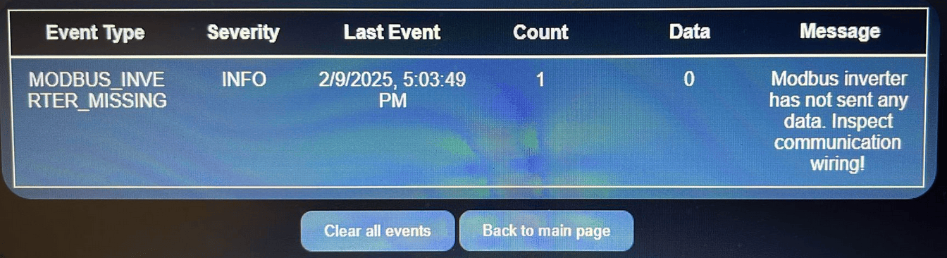
It means that the Modbus connection is down. Verify that:
- Polarity of M0+ and M0- is correct
- Protective earth is attached in both Inverter and Battery side
- Modbus cable shielding drain wire is attached only at one end
- Wires are seated correctly in the Fronius connector. It is very easy to miss that the wires are not pushed in all the way.
- Try a different power supply for the Battery Emulator board. Powering it via USB from a computer can cause noise on the signal output. Powerbank or phone charger might have cleaner voltage output. If you see strange modbus errors, your power supply might be noisy.
Make sure the Battery-Emulator has a good modbus connection to the Inverter.
- Use shielded twisted pair cable for a stable connection
- If you see
ModbusServerRTU.cpp [252] serve: RTU received: E5 - packet length errorin the logs of the board, it is an indication that wiring is not perfect and occasionally get corrupted
Invalid battery size detected~
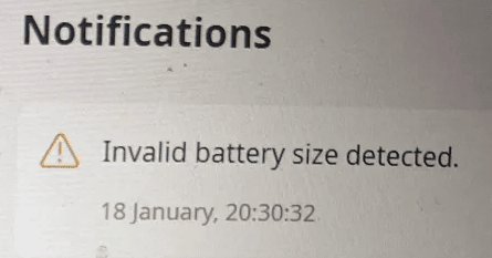
If you see this error, it might be because the battery you are using is having higher allowed maxvoltage than the Fronius inverter accepts. A good example is using BYD Atto3 battery (Max 460V), with a Fronius Primo single phase inverter, that only can take 450.
A quick solution is to enable the "450V maxvoltage cap" setting. This fakes it so that all batteries appear as 450V max.
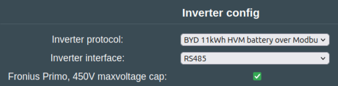
Note
This setting should not be used with Fronius Symo 3-phase inverters. These inverters are designed to work with battery voltages up to 700VDC.
Notes on reported capacity
Fronius inverters are designed to work with maximum 3x22kWh BYD batteries, and the protocol has a max value of 65535 Wh (unsigned 16bit value) for reporting Wh towards inverter. That means we have to restrict reported Wh number towards the inverter, for example when using a 75kWh Tesla battery, it will show up as max 60kWh in Fronius portal. This is just a REPORTED value, you can still use the full capacity of the battery. For instance, a 400kWh battery will be displayed as 60kWh, but the inverter will still be able to use the full 400kWh.
Other settings~
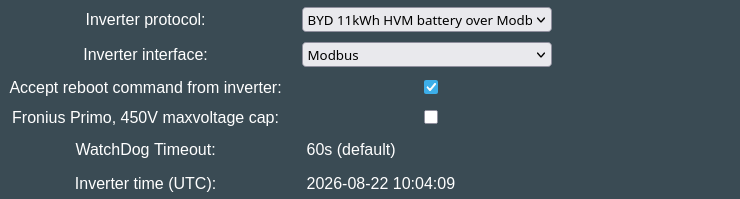
Accept reboot command from inverter, as the name says, when a non-zero RebootCommand is written by the inverter to Modbus register 407 will trigger the reboot of the emulator, pausing charge/discharge and opening the contactors first. Disabled by default, will raise an event. If you get this event, it's recommended to reboot Battery Emulator as soon as possible.
WatchDog Timeout is set by the inverter when it powers up, and is 60s by default. This is the time interval the inverter and Battery Emulator check each other for correct operation. It's persistently saved to flash. It's displayed purely for informational reasons, just like Inverter time (UTC), which is communicated by the inverter once per hour (shows "not yet received" after boot, until the first packets arrive).
Off-Grid/Backup Configuration~
Symo/Primo Gen24 inverters that are smaller than 6.0kW are not compatible with running full backup mode (the Primo 5.0 is). On these smaller inverters, your best bet is to utilize the PVpoint outlet to get power out of the battery.
A Smart-Meter is mandatory for battery use when connected to a grid (or generator). However, the Gen24 can run 'Off-Grid' if configured specifically for this scenario and limitations.
To run the Gen24 as off-grid but have the facility to connect to a grid (or generator) at some point, then you must follow the Full-Backup configuration design as documented by Fronius.
If you intend to never connect the inverter to a grid source (or generator), then you can hard wire the Gen24 in Full-Backup mode. In both cases, the smart-meter MUST NOT be detected when running in Full-Backup mode.
If needed for a future grid or generator power source, the smart-meter can be wired in as per normal ready for a grid or generator input, but the modbus comms (D+) must be disconnected to ensure it does not send data to the Gen24. If the gen24 detects a smart-meter when running in full-backup, then it assumes the grid is connected and will shutdown the inverter and not work reliably.
To hard wire the Gen24 as off-grid and 'cold-start' using the EV battery pack or PV, I/O pins 6 and 7 need to be jumpered to the V+ on the I/O connector as shown below.
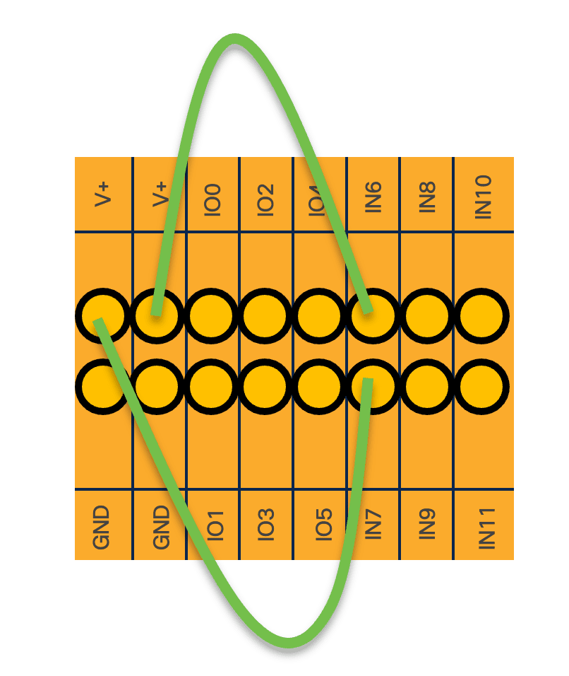
Additionally, Full-Backup mode needs to be configured on the Gen24 as follows:
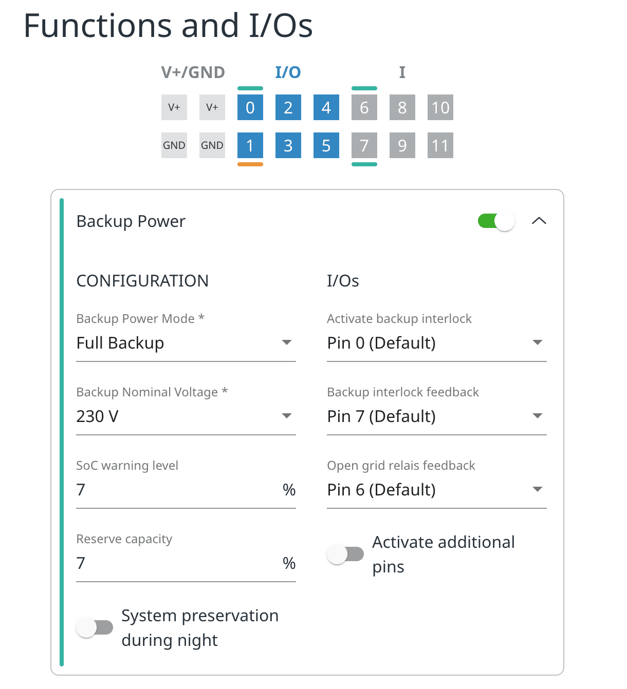
Pin0 is not used when hard wiring for full backup. Pin0 is used for automatic switchover to full-backup int the event of a grid failure. Follow the Fronius documentation for this type of configuration.
The Fronius Gen24 configuration documents describe both automatic and manual switch-over to backup mode using combination of switches and/or relays. Both options can be commercially sourced if you need a non hard-wired off-grid only solution.
NOTE
When running as Full-Backup, the inverter will run by default at 53Hz. As such, no other inverter can be active on the AC circuit. Only the Gen24 can be providing power! If you need additional power, then a true Micro-Grid should be used (AC coupling with Victron etc).
IMPORTANT
Fronius officially supports a maximum of 2000h off-grid (full-backup) per year on the Gen24. Exceeding this hour count voids the warranty. There are no reports of any inverters shutting down after 2000hours.
To get around this off-grid limitation, you can create a microgrid using a 48V battery that powers a small inverter, and then connect the Gen24 to this microgrid. Then it will be essentially offgrid, without incrementing the 2000h max counter. Example of this running successfully has been done with a Victron a 7.2kwh(LV) , and FroniusGen24 with a 75Kwh battery(HV). A smart meter is required if running as a true micro-grid.
All normal earthing requirements when running in 'off-grid' must still be followed. Consult a qualified electrician for advice.
Advanced control of energy (Spot price, scheduled charge/discharge etc.)~
Once you have your battery connected to the Fronius, it is possible to add additional hardware into the mix for advanced control of how energy should flow in the system. This is useful for those with spot-price electricity, or a nightly tariff. Below are some examples you can utilize to control the Fronius Gen24 directly via Modbus TCP.
- You can setup forced nightly charging via the webinterface of the Gen24 (Requires connecting to the inverter directly, not available via SolarWeb). This is very useful if you have a cheap night tariff, and want to charge the battery during the night and use the energy during the day
- Arska-node reads Nordpool electricity prices (from EntsoE/Elering) and renewal energy forecast (solar from Open Meteo, solar/wind from Finnish FMI) as well as local real-time net power consumption/sales (smart meter HAN P1-port -tested in FI, Shelly 3EM). Based on this and time based data (+ optional ds18b20) the system updates variables (github/Netgalleria) which are used in channel rules deciding whether the channel should be up/down/charging/discharging. Arska has also basic load management functionality (limits loads if consumption exceeds given limits). So far users have used the system mainly to optimise self-consumption of PV production and for scheduling flexible consumption at the cheapest time and selling any surplus when the price is high. Arska has controlled (through GPIO, Shelly and Tasmota relays) water boilers and (underfloor) heating. According to the developer, version 1.3 controls the Fronius GEN24 charging/discharging parameters (nWRte, OutWRte, StorCtl_Mod) based on given channel rules.
- Info on how to control Fronius Modbus via Homeassistant (German)
- SBAM: Charge Fronius battery using SolCast weather forecast
- This integration gives you full control over the charge and discharge of the battery.
CAUTION
Working with high voltage is dangerous. Always follow local laws and regulations regarding high voltage work. If you are unsure about the rules in your country, consult a licensed electrician for more information.