BMW i3 60/94/120AH~
Compatible BMW batteries~
All i3 batteries have the following length/width/height 1660mm x 964mm x 174mm.
- BMW i3 60 Ah, 18.2 kWh, 233kg, 2013+
- BMW i3 94 Ah, 27.2 kWh, 256kg, 2017+
- BMW i3 120 Ah, 37.9 kWh, 273kg 2019+
- Mini Cooper Electric (F56) 94Ah, 32.6kWh 2019+
Word of caution when buying i3 batteries ⚠️~
IMPORTANT
The BMS (SME) inside the i3 battery will store crash data. If the battery comes from a really hard crash that triggered enough airbags, there is a possibility that the SME has entered a locked state, and will never engage the contactors. The only way to unlock the battery is with an expensive BMW tool called "EoS Tester" that costs 10k€. Update: According to a user you can swap the SME board with one from eBay or other places online and it will work with battery emulator, though not with a BMW i3 since it will need to be EoS tested.
CAUTION
When shutting down a working i3 battery system, no load can be present on the HV circuit. First shut down inverter before shutting off the battery, OR use the PAUSE button in the Webserver to ensure that 0A of current before shutting down the battery. The i3 has extremely sensitive welding detection. If there is over a few A of current during opening of contactors, it will set the "Contactors Welded" state and lock the battery permanently.
The EoS tester can be rented from some places, a great i3 expert is available in CZ, i3upgrade Another alternative when dealing with a locked battery, is to open up the battery and bypass the contactors. Nobody has reported if this works yet (feel free to edit this wiki!), worst case you could also replace the i3 BMS with an RJXZS
An indicator if the battery is not in lock state is the range indicator of the crashed car. If it displays battery range/percentage, the battery is probably not in lock state even if a few airbags have gone off.
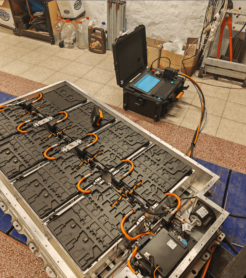
Crashed BMW i3 battery being reset with an EoS tester:
Software configuration~
For this battery type, use the option called "BMW i3" under the "Battery Protocol" setting.

Connection diagram~
High voltage connector~
Right beside the HV connector there is a plug with 2 small pins, these need to be bridged either with the original plug, or shorted with a jumper for the battery to be able to turn on (Interlock detection)
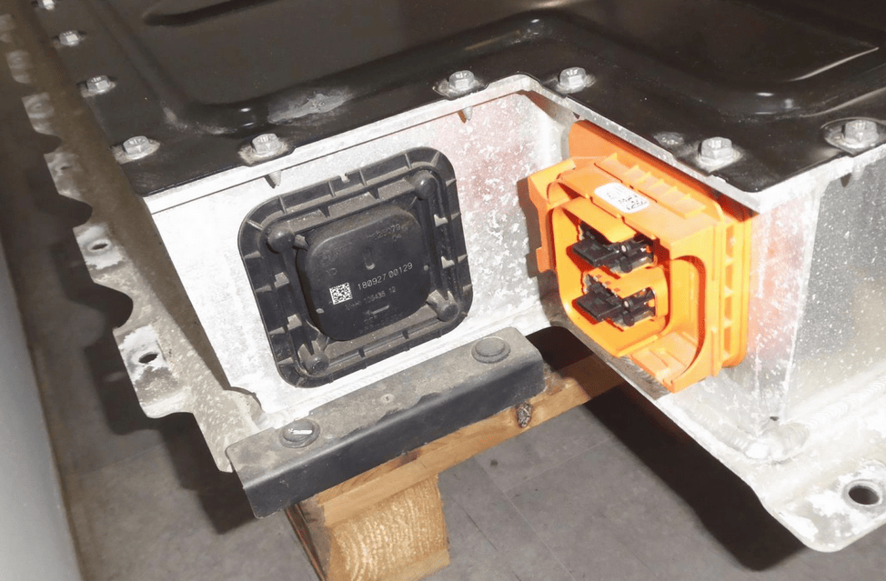
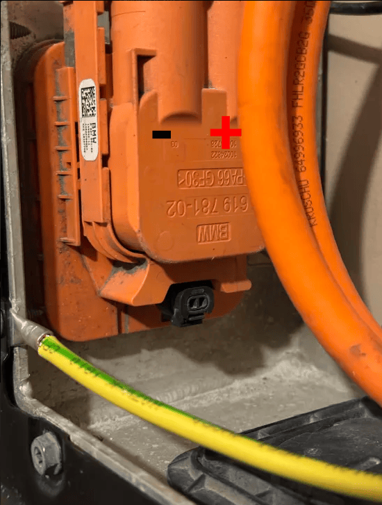
High voltage connector (E196*1B)~
- Pin 1 = HV+
- Pin 2 = HV- The HV connector has + and - marked on it.
HVIL part of high voltage connector (E196*01B)~
- Pin 1 HVIL (loop to 2)
- Pin 2 HVIL (loop to 1) Can also be bridged with jumper wires.
TIP
Check out our High Voltage wiring page with examples on how to make the connections safely.
Low voltage connector (A191*1B)~
The LV connector is located on the back of the battery pack, next to the A/C cooling port. A/C connector is not required for operation.
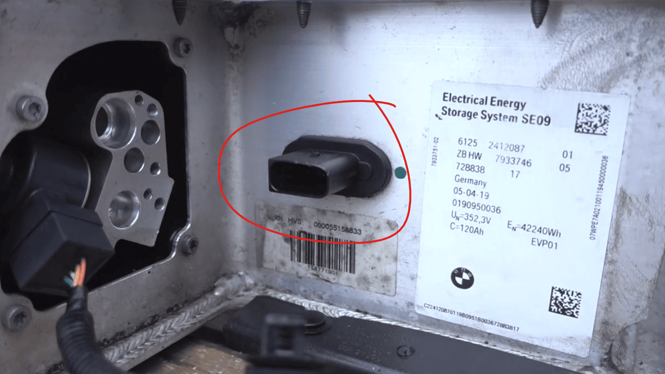
It has the following pinout:
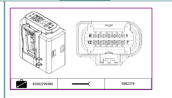
Connect the wiring as follow:
- Pin 1 30C - Connect to 12V, 10A fuse optional
- Pin 9 15WUP-Signal (Green/GreenRed) - Connect to 12V, 5A fuse optional. Control this pin with ASR-10DD relay or a Pololu Power Switch controlled by the WUP GPIO pin of your board (see the list below).
- Pin 7 (Red) - Connect to 12V, 5A fuse optional
- Pin 2 Ground (BrownBlack) - Connect to Ground
- Pin 4 CAN-H (WhiteYellow) - Connect to CAN-H on the board - twist with CAN-L cable and put a 120Ω resistor across to CAN-L.
- PIN 10 CAN-L (WhiteBlue) - Connect to CAN-L on the board
- Pin 6 I_LOCK (BlueRed) (connect to Pin 12 with a 33Ω resistor in between)
- Pin 12 I_LOCK (BlueRed) (connect to Pin 6 with a 33Ω resistor in between)
- Pin 3 Refrigerant valve (NOT USED)
- Pin 8 Refrigerant valve (NOT USED)
15WUP-Signal~
The GPIO that controls the WUP signal depends on your BE hardware:
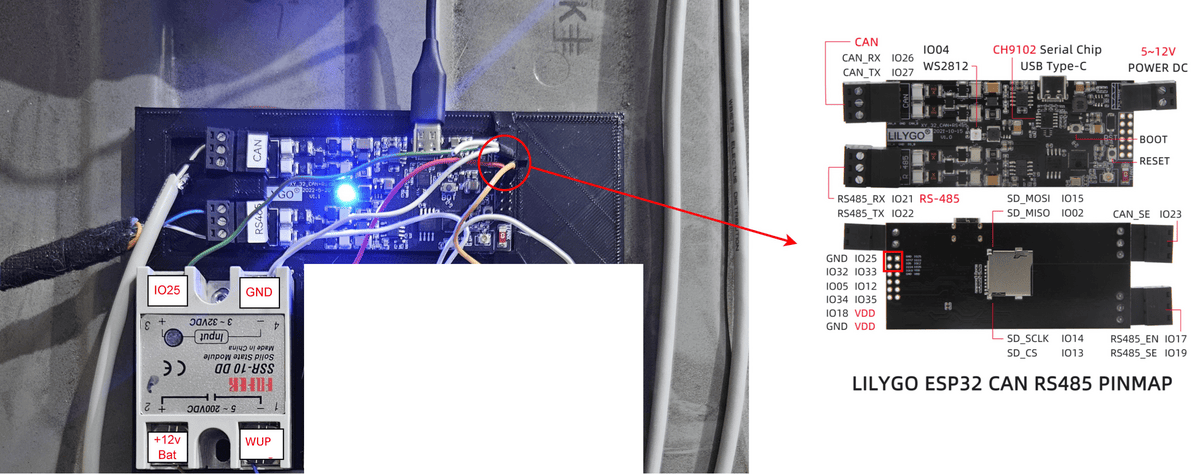
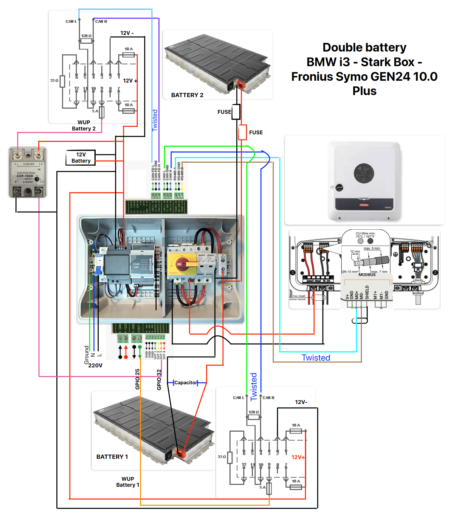
- LilyGo T-CAN485: GPIO 25 (For double bat GPIO 32 is used for secondary BMW i3 battery)
- Stark CMR: GPIO 25 (For double bat GPIO 32 is used for secondary BMW i3 battery)
- LilyGo T-2CAN: GPIO 40 (For double bat GPIO 38 is used for secondary BMW i3 battery) -Since a recent update WUP has been moved to GPIO 1! This requires you to buy qwic wires or jst sh 1.0. These can be found on Amazon or AliExpress with a few cm or wire crimped to them.
The wakeup signal needs to be actuated by the Battery-Emulator, and as soon as messages start to come through from the battery we reply. This ensures a reliable startup. Same goes for rebooting/shutting down the battery. The Battery-Emulator sets WUP to low incase we need to command the BMS off.
Since the board has 3.3V logic on the GPIO pins, we need to use a solid state relay in order to boost the 3.3V -> 12V. Example connection using 1x ASR-10DD solid state relay:
CAUTION
To avoid welded contacts Ensure you have a 12V backup system to avoid unwanted contact closings under load in case of a blackout.
TIP
Check out our Low Voltage wiring page on how to make the connections in practice.
Example wiring diagram~
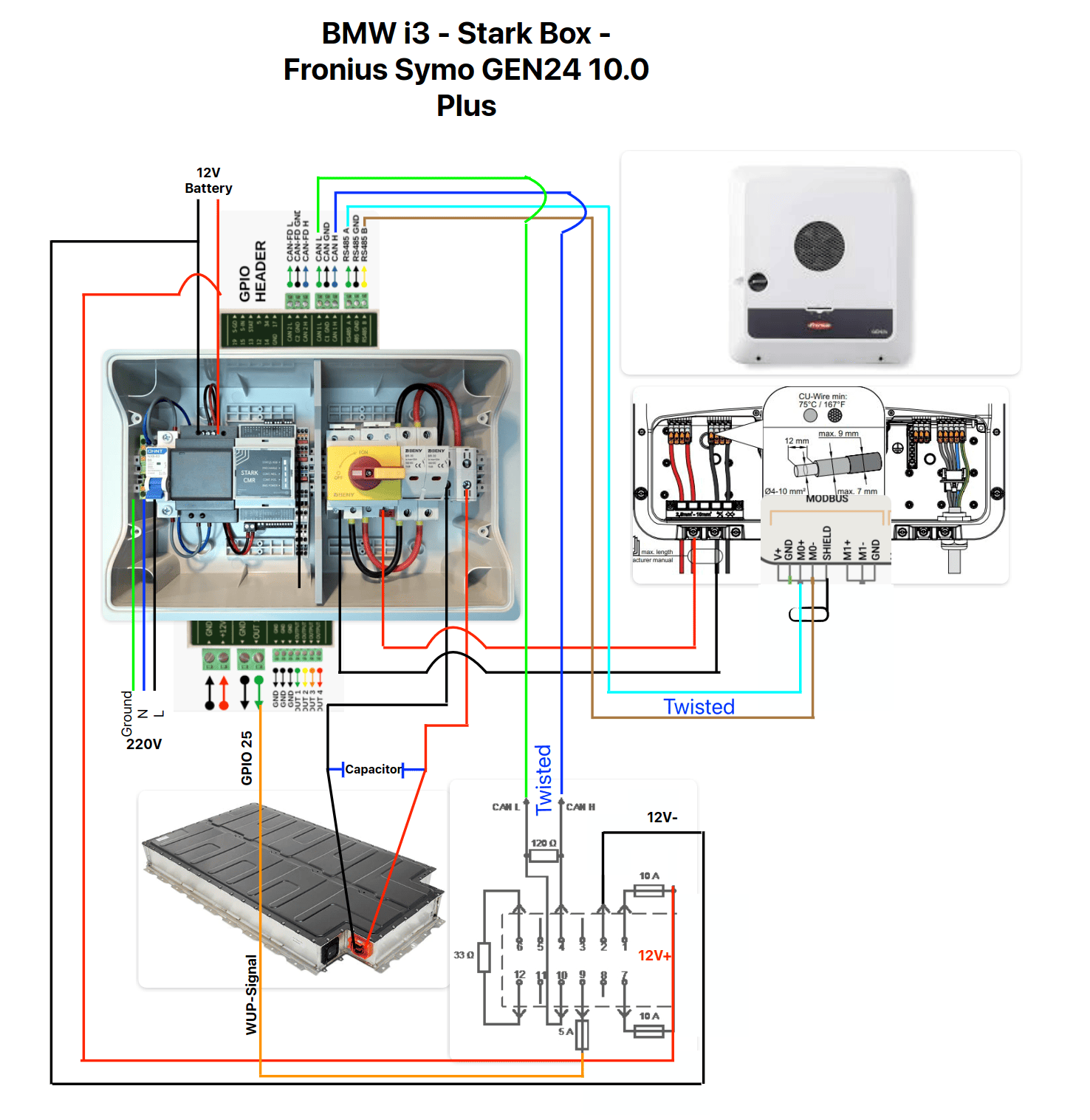
Below an example wiring diagram:
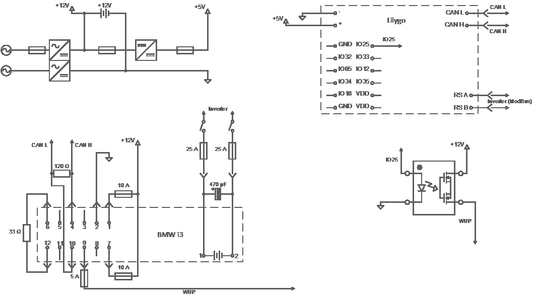
Stark Box + i3 battery + Fronius Gen24~
Stark Box + 2x i3 battery + Fronius Gen24~
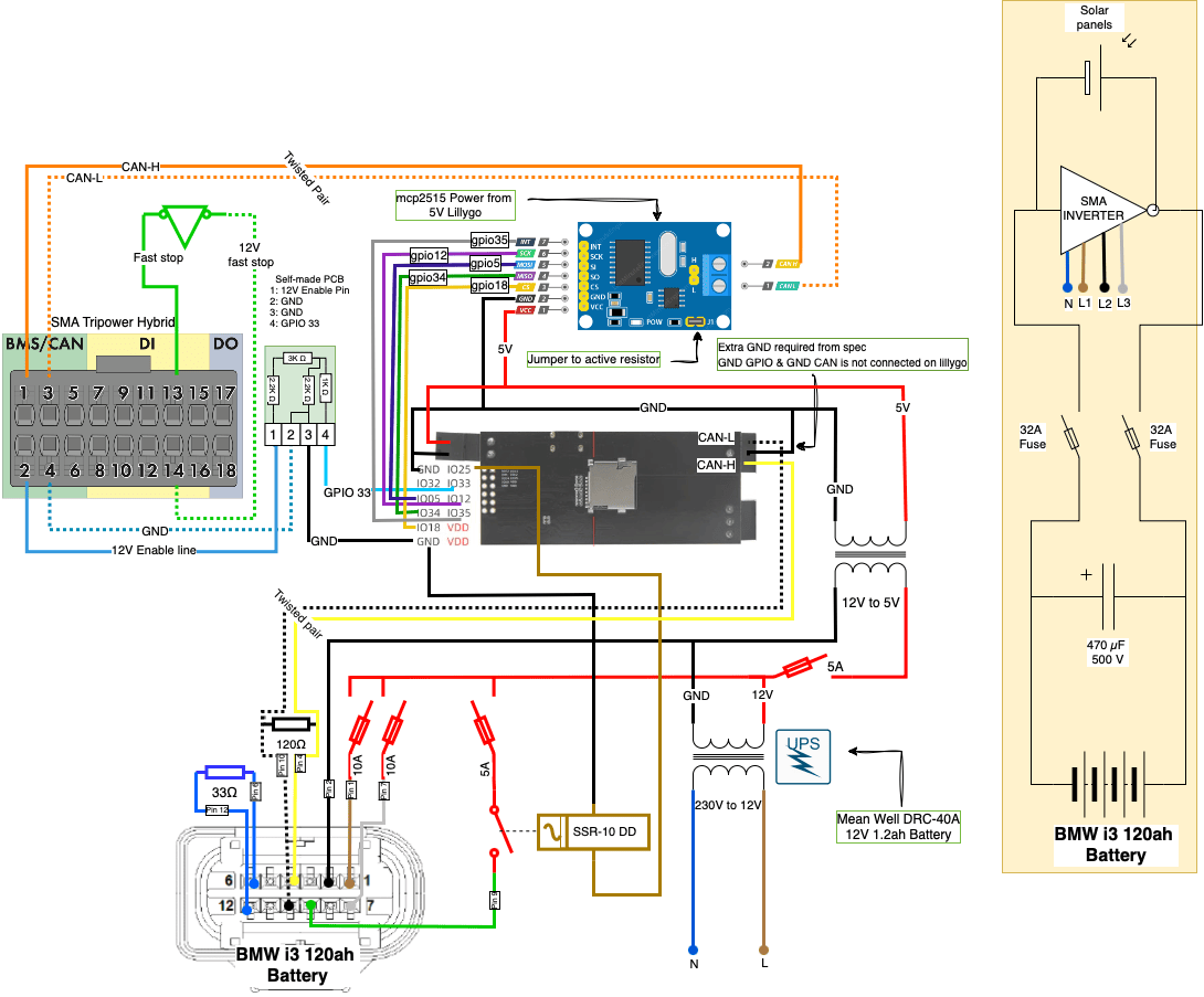
SMA Sunny Tripower to Liligo and BMW i3~
Parts list~
- BMW i3 battery
- 60Ah
- 61252353679 / 140116 / 7625051 / 2353644 / 728838
- 94Ah
- 61252412020 / 72883817 / 8647909 / 14191812
- 120Ah
- 2412116 / 2412117 / 7933745 / 7933746 / 7933747
- BMW HV cable
- 61129346573
- 61126809274
- 761978102
- BMW CAN Connector
- 61139165781 (also known as 9165781).
- Note: equivalent part from Kostal is # 9411204.
- Pigtail, easy: Link to Aliexpress
- Pin your own: Link to Alibaba, You can order a sample instead of multiple connectors
- This includes MQS bushing contacts, no wires attached
- Search suggestion "12 Pin 9165781-01/76616-9"
- HV Capacitor 470µF or higher and more than 500V.
- Consider a capacitor with screw connection to avoid the need of soldering iron
- 33Ω resistor, ¼ watt or similar is fine.
- 12V power supply (When Grid-backup is not available)
- with UPS to avoid welded contacts)
- E.G: Mean Well DRC-40A with a 12v 1.2ah battery
- with UPS to avoid welded contacts)
- BMW HVIL bridge (can be use a piece of copper wire)
- 12527630408
- 8x BMW Bushing contact MQS with cable for CAN connector (optional)
- 61130030859 / 61130005197 (they are all the same color though, recommend to mark them)
- Or get a free wiring harness from your scrap dealer and reuse the cables
Note on capacitor~
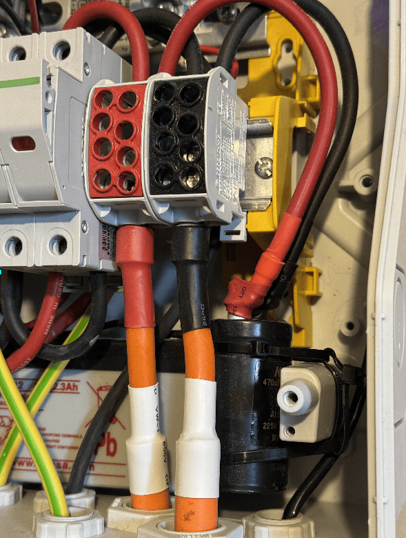
Capacitors are high voltage, so they need to be inside an IP enclosure to prevent anyone from touching or water getting onto it and shorting it out. Most either mount the capacitor next to the battery, or next to the inverter, at either end of the HV bus. The most popular solution is to install fuses and the capacitor right at the start where HV comes out of the battery, sort of an add-on box that gets mounted on the original HV cable coming out of the battery. This is also a good place to step down the batteries thick DC cabling (35mm² in case of the i3), down to a more manageable 10mm². Check out our High Voltage wiring page with examples on how to make the connections safely.
Example of capacitor integrated at point where wire gauge is reduced, inside exclosure:
Note on Balancing  ~
~
The BMW i3 battery needs periodic cell-balancing to be able to operate at full capacity. To start this balancing procedure, charge the battery to 100%, and go to the "More Battery Info" page on the Webserver. There is a button called "Start balancing". When balancing is started via this page, the battery will power off the wakeup(WUP) pin towards the battery, stop CAN communication, and the battery can then start to balance, just as it would in a car.
Perform this balancing as often as necessary to keep cell mV delta low. Failure to balance will longterm lead to much capacity being unavailable due to voltage diff, along with wildly incorrect SOC% readings.
Important info when used with BYD CAN inverter~
NOTE
If you intend on using BYD-CAN with the BMW i3, the battery needs to be on a separate CAN bus. The BMW i3 is using the same CAN IDs as BYD do, so if you try to run them both on the same bus the IDs will collide and values get interpreted wrong.
Troubleshooting tips~
| Problem | Suggested fix |
|---|---|
| Contactors not closing | Check that the capacitor is seated between HV+ and HV-. Check that negative and positive are not accidentally shorted together. Worst case scenario HV fuse inside battery is blown and requires replacing |
| Event "Error: Battery interlock loop broken. Check that high voltage / low voltage connectors are seated" | Check that both interlocks are OK. 1. The High Voltage needs to have the two small HVIL wires joined together near the orange connector. 2. The Low Voltage connector also needs to have pin 6 and 12 connected via a 33 Ohm resistor. If you are doing the pins yourself, make sure they are seated all the way. |
Example completed setup~
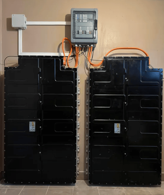
Fronius Gen24 with 2x BMW i3 batteries in double battery mode
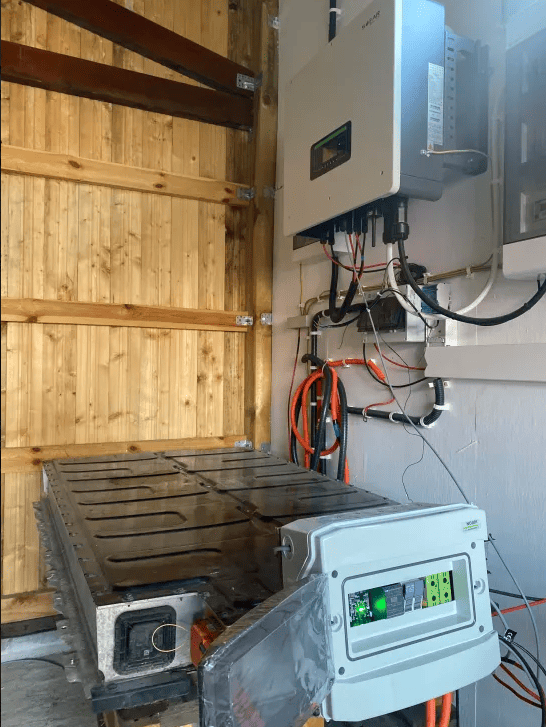
i3 94Ah with Sofar inverter
CAUTION
Working with high voltage is dangerous. Always follow local laws and regulations regarding high voltage work. If you are unsure about the rules in your country, consult a licensed electrician for more information.