Volvo SPA XC40, C40 / Polestar 2~
CAUTION
Battery can lock itself permanently if started without DC-DC converter on HV side! You have been warned, please read the Wiki carefully!
Measurements~
148x176cm and about 500kg
Battery specifications~
The following SPA platform batteries are compatible, checkbox on those confirmed by users to work.
- Volvo XC40 2021-present
- 64 kWh (usable), 69 kWh (gross) ✅
- 75 kWh (usable), 78 kWh (gross) ✅
- 79 kWh (usable), 82 kWh (gross) Extended range ✅
- Polestar 2 2020-present
- 64 kWh (usable), 69 kWh (gross) Standard range ✅
- 75 kWh (usable), 78 kWh (gross) Long range ✅
- 79 kWh (usable), 82 kWh (gross) Long range ✅
Software configuration~
For this battery type, use the option called "Volvo / Polestar 69/78kWh SPA battery" under the "Battery Protocol" setting.

Buying tips~
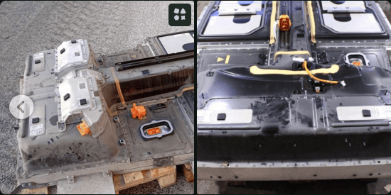
Make sure the contactor assembly (Left picture, silver box) is included with the battery. Some places remove it and sell it separately. Without this you wont get contactors,current sensor, precharge, fuses etc., rendering the battery unusable.
NOTE
It is OK to buy a battery from an airbag crashed vehicle. It is possible to clear that fault code via the "More Battery Info" page.
CAUTION
If you want to use Battery-Emulator to read info, check cells, on a standalone battery before buying, comment out any sending of 0x140 messages in the VOLVO-SPA-BATTERY.cpp file. Otherwise it will try to close contactors, and without the DC/DC converter it will permanently lock the contactors as welded. See further down for more info on DC/DC requirement.
Wiring diagram, low voltage~
Connect HVIL2_EXT_IN and HVIL2_EXT_OUT together with a cable. (this will close the HVIL loop in BECM.) Dont forget the driveline connector. When using the 4wd it's only for on the connector to the rear axle. If you have a different type it can be multiple connectors. For the wiring diagram see loopybunny
The BECM has no built in 120ohm resistor. (BECM = Battery Energy Control Module) Make sure the terminating resistors are correct. CAN networks should have two 120 Ohm resistors in each end of the network. With everything OFF, you can measure resistance between CAN-H and CAN-L. The result should be 60 Ohm. You can connect a 120ohm resistor between pin 44 and 45 to terminate the bus in the BECM end.
Attached below are pictures of the BMS pinout. Connect the pins to the Battery-Emulator hardware and 12V supply like this:
- Pin 42 to CAN-H on the board
- Pin 43 to CAN-L on the board
- Pin 44 - 120ohm termination resistor - Pin 45
- Pin 24 & 33 to +12V
- Pin 47 This wire needs to be connected to the battery casing for isolation measurement
- Pin 48 12v GND (47 and 48 are internally connected)
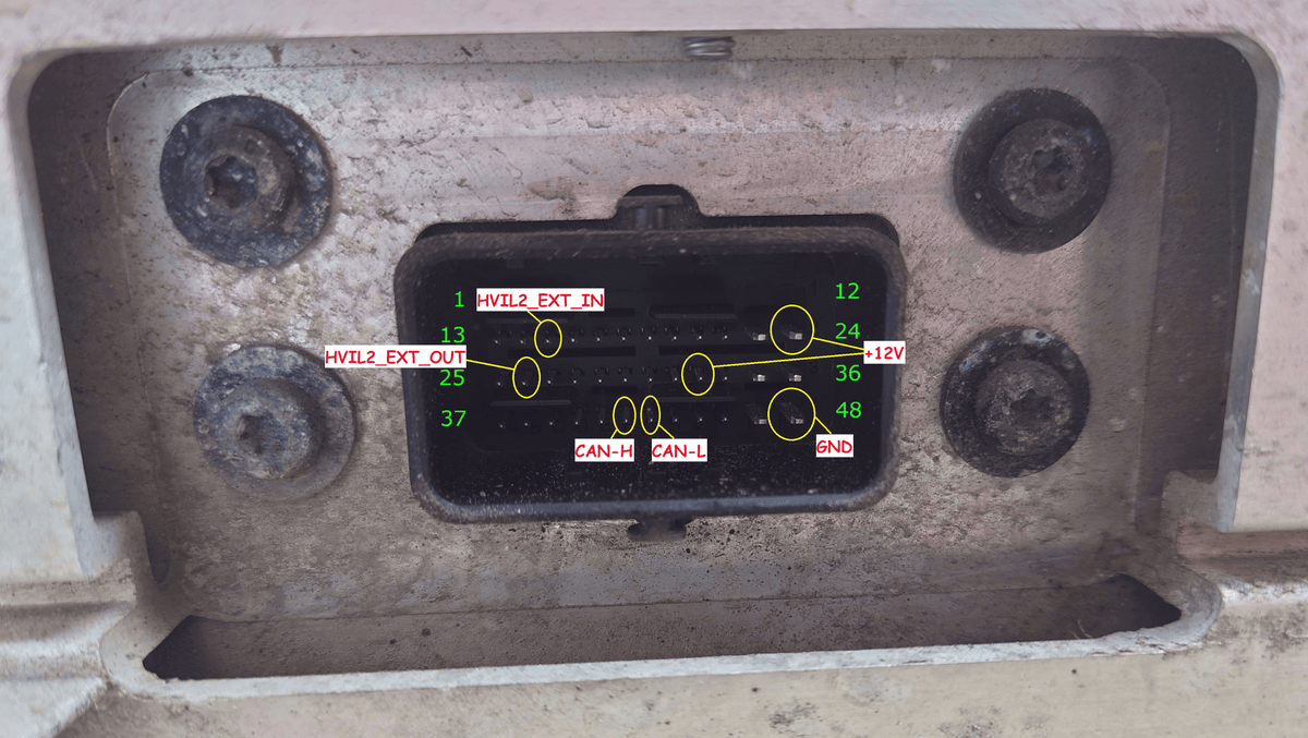
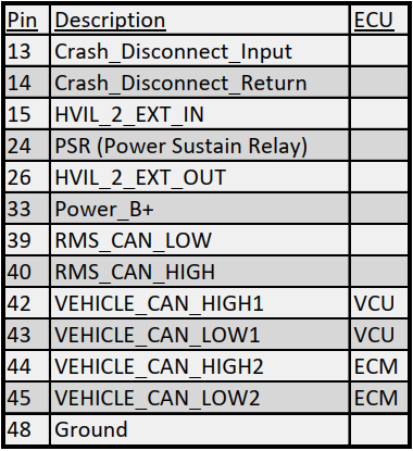
To use the CAN contactors on Volvo XC40 and Polestar2, you need to connect the GND from the battery connector (PIN47) to the battery case. This GND is used for insulation monitoring. Without it, the battery will not be able to check the insulation integrity and will not engage contactors.
Wiring diagram, High voltage  ~
~
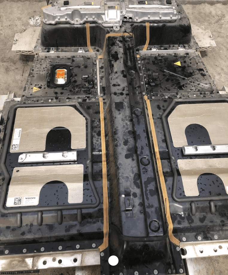
Here are the ports that you can use on the battery to get voltage out:
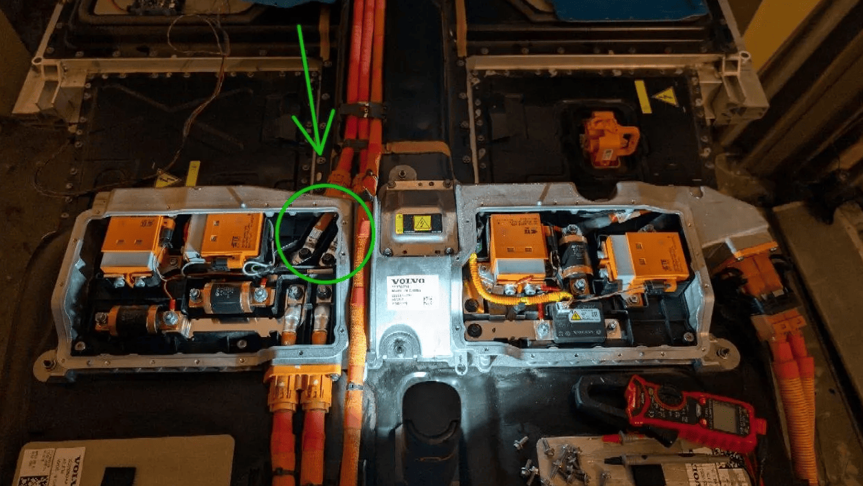
Positive LH, Negative RH
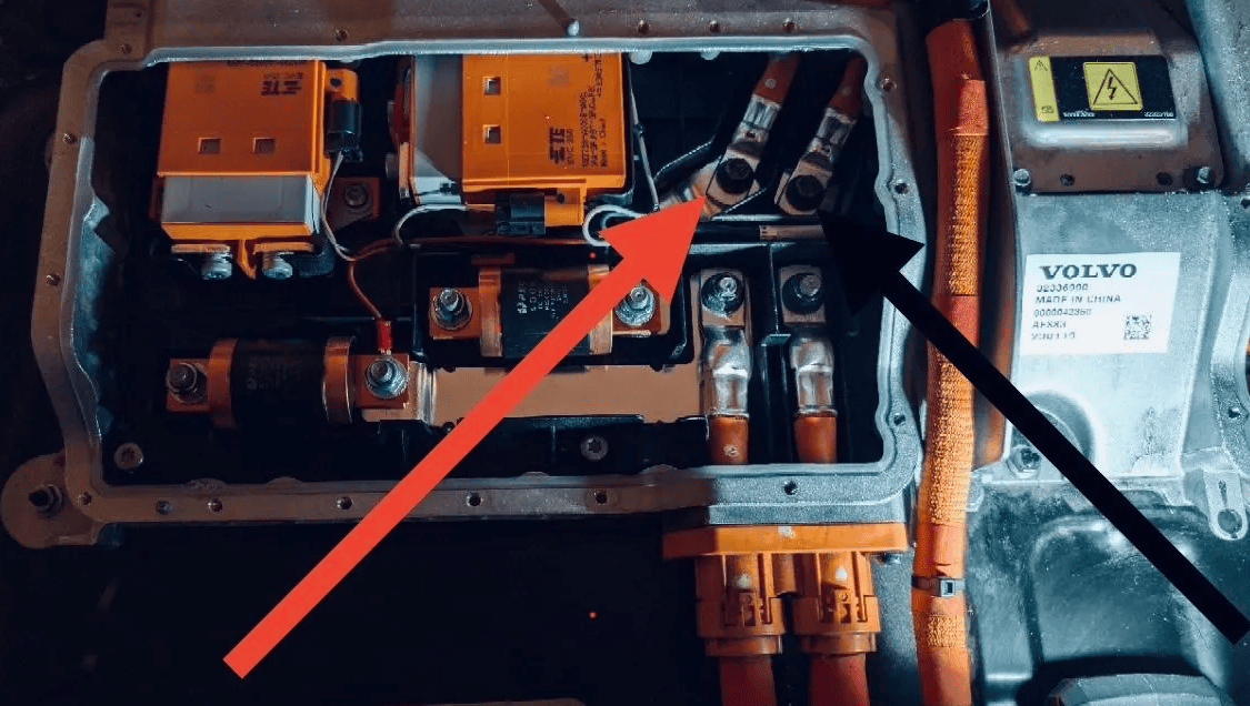
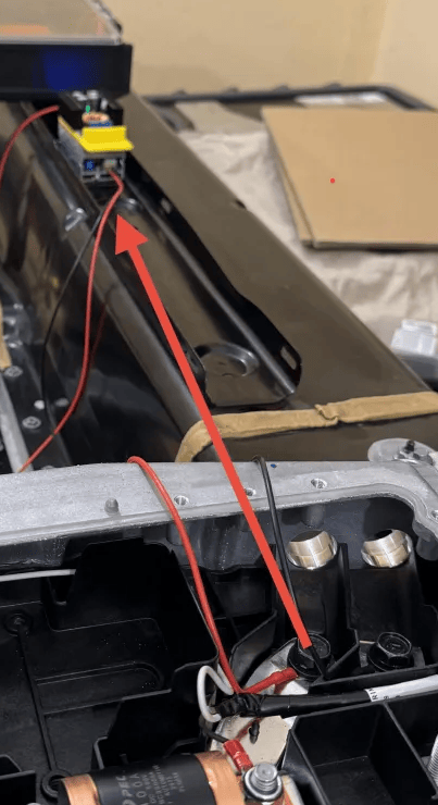
Test wires attached:
CAUTION
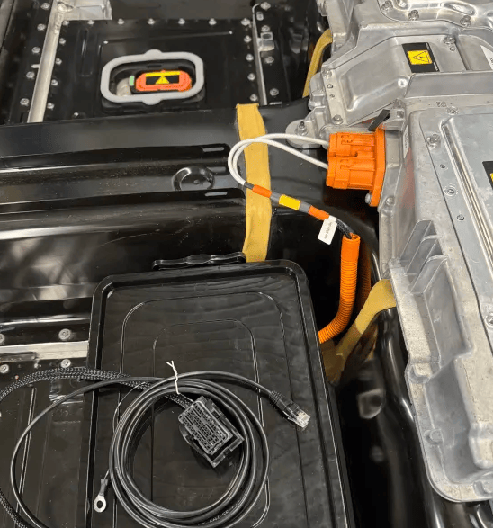
Battery can lock itself permanently if started without DC-DC converter on HV side!
In order to start the battery you need to have capacitance and current draw ready on HV lines. This can be achieved by connecting a DC-DC converter (which you can purchase from the link below) to the high-voltage output from the front motor. If you skip this step and try to start the battery directly, an irreversible fault code will trigger (Contactor welded). After this fault code is set, you won't be able to engage the contactors via the CAN bus anymore.
Connect the DC/DC converter to the high voltage output lines shown above. Pay attention to the polarity to avoid damaging the DC/DC converter.
The DC/DC converter can also be used to charge a 12V lead acid battery, or left totally unused. The purpose of it is to mainly just enable contactors safely without triggering any fault codes.
DC/DC connected:
Part numbers~
Incase your battery is missing some wires/disconnect switches, here are the OEM part numbers and purchase links. Do note that it might be cheaper to source from your local scrapyard!
| Product | Purchase Link |
|---|---|
| Service disconnect switch 32324494 | Volvoshop |
| Low voltage 48pin connector | Aliexpress |
| Low voltage 48pin connector with cable (take black one) | Aliexpress |
| DC-DC converter | Aliexpress |
Handy tips  ~
~
Contactor closing with Deye 30kW, 50kW ,Solis S6-series and Fronius Gen 24.~
There is a known issue with Deye inverters, that when starting it up with a Volvo battery that requires DC/DC power present, there is a risk that the Deye will cause an isolation issue that prevents contactor closing.
To solve this, Power off inverter by switching off the grid and PV. After the inverter has shut down, you can power on the battery. After it powers on, and the invertor starts, than power one the grid and PV connection. So basically the battery needs to be the thing that starts the Deye, Solis and Fronius first.
You will also need a robust 12V power supply, as contactors (models from 2024 onward) draw approximately 30–40W.
Opening the contactor assembly~
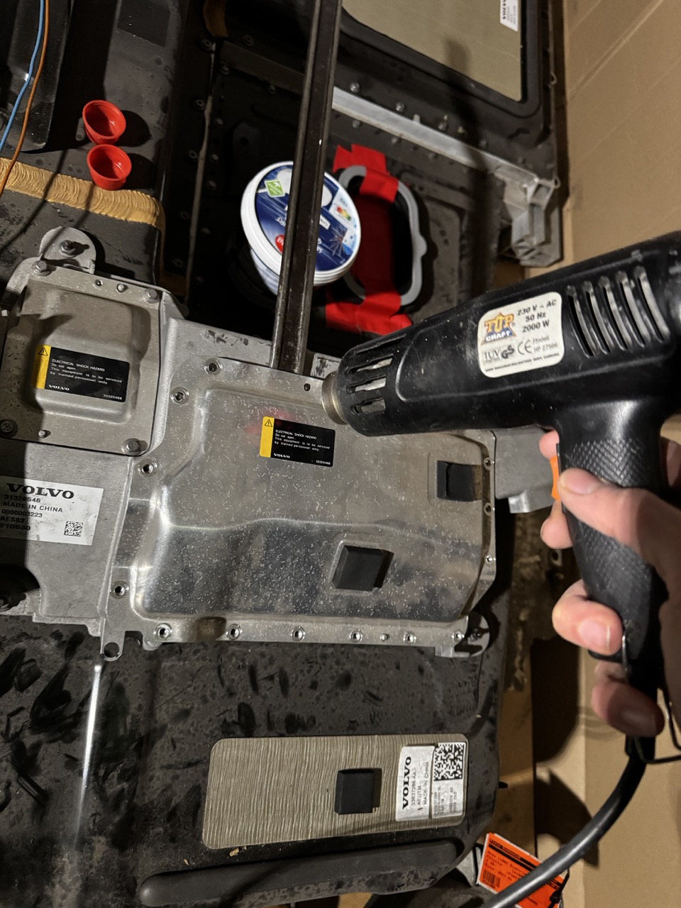
Use a heat gun to warm up the glued seal between the cover and the bay. Use a lever to open the cover then.
No CAN comm issue~
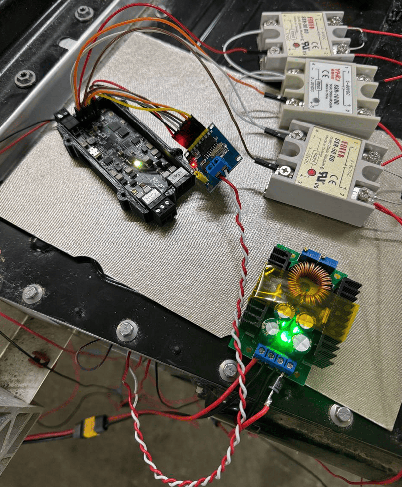
When 12V power is applied to the battery and the Battery-Emulator hardware, there is occasionally an issue where the CAN bus and the transceiver in the BMS control unit do not "wake up," making communication impossible. So far, I’ve found only one solution to this problem — adding an external MCP2515 module and configuring it for communication with the BMS. In this setup, everything works smoothly and without any issues, ensuring reliable data transmission over the CAN bus.
Another thing to test if issue with comm is to leave pin 24 (+12V) disconnected during the first startup of BECM.
Reading DTCs~
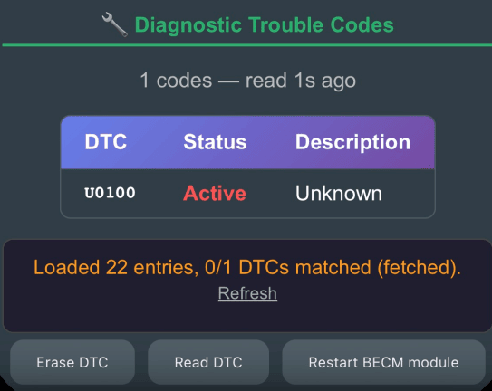
To read Diagnostic Trouble Codes, go to the More Battery Info page and press Read DTC.
Unlocking a permanently locked BMS~
If the BMS is permanently locked, replacing the BMS is the easiest solution.
There is a chance that reflashing the BMS can help, but the success rate is low. Some .hex files available on Discord.
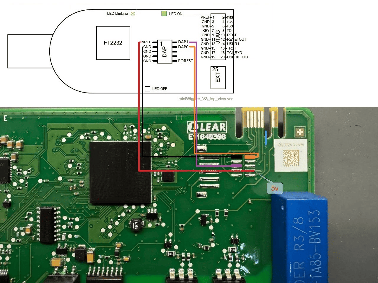
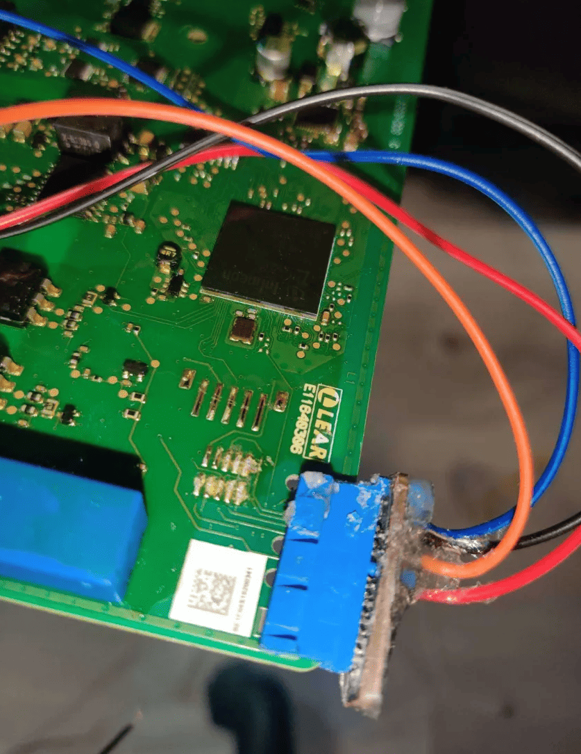
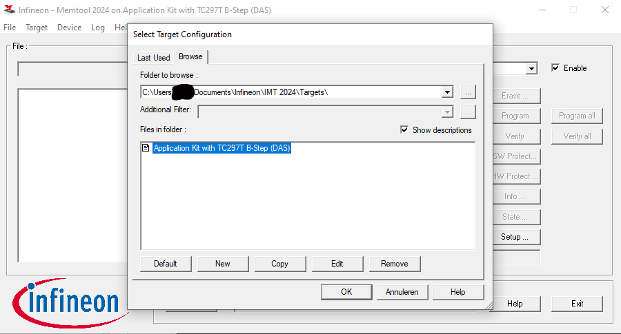
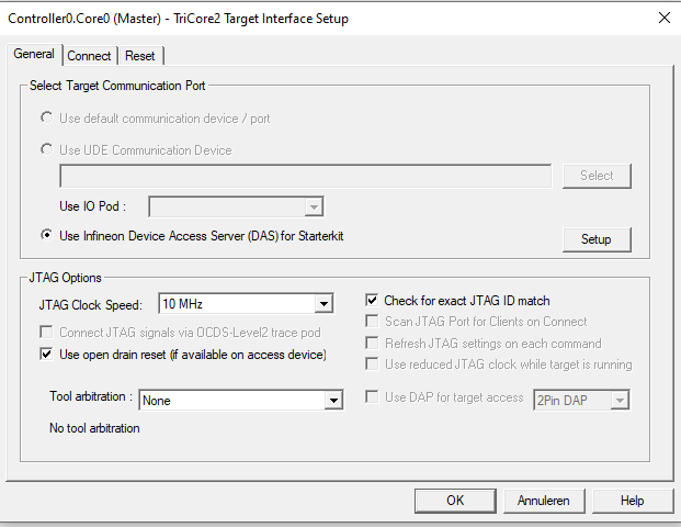
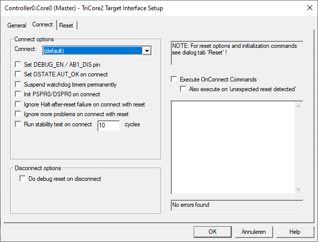
Miniwiggler v3 dap attached to BMS board via PCI-e from old motherboard to avoid soldering.
Flashing tips;
- External 5V to VREF and GND is required
- If it is toggling "Device has no ID register", the supplied current might be too low. You must apply external 5v with around 1A
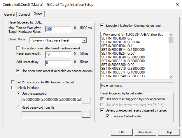
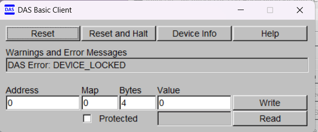
- If you cannot make connection with memtool, it could be that access is blocked via code, see picture below. password is unknown until now, if blocked like picture then BECM board needs to be swapped
CAUTION
Working with high voltage is dangerous. Always follow local laws and regulations regarding high voltage work. If you are unsure about the rules in your country, consult a licensed electrician for more information.